|

-
Oct 6th, 2015, 02:34 PM
#1
Thread Starter
Lively Member

 [RESOLVED] Maths issue: coordinate systems [RESOLVED] Maths issue: coordinate systems
Hi all,
frightfully bad with maths... but perhaps I could describe my dilemma, and get a bit of specific help?
I have a coordinate system, and then a second system. The scale is the same, but the direction of one axis is inverse to the other, and the position and rotation can not be known in advance.
I can "calibrate" one coordinate system to the other... so that I can take some set of two or more points, and know what that point represents in BOTH systems.
Armed with that information... how can I map any hypothetical point in one system, to the other?
(Apologies if this is not the right location for this kind of question)
Thanks for your kind help,
R
-
Oct 6th, 2015, 03:08 PM
#2
Hyperactive Member

Re: Maths issue: coordinate systems
--- EDIT ---
My answer was trumped by Boops Boops 
---
Last edited by Frabulator; Oct 6th, 2015 at 03:12 PM.
-
Oct 6th, 2015, 03:10 PM
#3
Re: Maths issue: coordinate systems
Typically it's the Y axis that is reversed in VB.Net compared to conventional coordinates. It points down instead of up. In this case, all you need to do is the reverse the sign of the Y coordinate. For example to reverse a point:
Code:
Dim P2 As New Point (P1.X, - P1.Y)
But it might be more convenient to leave the points unchanged regardless of the axis direction. For example, you could plot the points to a bitmap (bmp) then reverse it using the RotateFlip method, for example:
Code:
bmp.RotateFlip(RotateNoneFlipY)
If you want to flip in the X direction, use RotateNoneFlipX.
By the way, we do have a Math forum but this is fairly trivial as mathematical problems go.
BB
-
Oct 6th, 2015, 03:22 PM
#4
Thread Starter
Lively Member
Re: Maths issue: coordinate systems
Thank you for your kind reply.
I'll try to explain in greater depth, which will hopefully answer all of your questions.
I have an X,Y system, in millimeters, that we may say is not rotated. The origin is in the center. Positive values are Up and Right.
I have another system, in millimeters, that we will say is rotated with respect to the first, but cannot be known before calibration.
This system has the same x-axis direction, but the Y axis is inverted (positive values down).
I can lay one over the other and calibrate them... (literally, in the real world)... and for any number of points necessary, I can know the coordinate location on each system.
Now I am looking for a methodology to take this calibration... and be able to know both when I know only one.
As far as how to assert rotation... I'm confused about how to do that I would say that I am uninterested in the absolute rotation, only the coordinate to coordinate mapping. Any method that is easiest to capture the rotational component is fine. I think that the calibration points must somehow indicate a rotation... but apart from needing it for remapping, I have no interest or use for it.
Best regards,
R
-
Oct 6th, 2015, 03:42 PM
#5
Thread Starter
Lively Member
Re: Maths issue: coordinate systems
 Originally Posted by boops boops

By the way, we do have a Math forum but this is fairly trivial as mathematical problems go .
BB
Oh my, I didn't see it... but I'll look again. I am happy to move it there.
I suspect that it's not going to be trivial... there will be matrix multiplication happening almost certainly.
Please see my expanded explanation of what is happening.
Thanks so much!
-
Oct 7th, 2015, 07:02 AM
#6
Re: Maths issue: coordinate systems
Coordinate mapping is a trivial/basic operation. While matrix manipulation may be involved, at its simplest level, for linear axis, the equation y=mx+c is all you need for each axis. This will work for 'rotated' translations, if the actual angle of rotation is unimportant: it will still translate the same. Even so, you may be able to determine rotation angle if required.
"Ok, my response to that is pending a Google search" - Bucky Katt.
"There are two types of people in the world: Those who can extrapolate from incomplete data sets." - Unk.
"Before you can 'think outside the box' you need to understand where the box is."
-
Oct 7th, 2015, 12:18 PM
#7
Thread Starter
Lively Member
Re: Maths issue: coordinate systems
Originally Posted by SJWhiteley
Coordinate mapping is a trivial/basic operation. While matrix manipulation may be involved, at its simplest level, for linear axis, the equation y=mx+c is all you need for each axis. This will work for 'rotated' translations, if the actual angle of rotation is unimportant: it will still translate the same. Even so, you may be able to determine rotation angle if required.
How can you map between rotated coordinate systems properly, without knowing at least something about rotation?
Anyway, if it's trivial, then why has nobody presented a solution? (perhaps y=mx+c? But I have no idea what this means or how to use it)
I have heard about using matrix manipulation to solve this problem, but so far, no one has described how to use it.
What I am getting from this up to this point, is that remapping from one coordinate system to another (2D), involves a single translation, and a single rotation. Is this a correct statement?
I also think that I am hearing that to do a conversion in the opposite direction, one merely needs to change the signs of the translation and rotation. Is this also a correct statement?
Thank you for your kind help on this!
R
Last edited by RyderS; Oct 7th, 2015 at 12:29 PM.
-
Oct 7th, 2015, 12:29 PM
#8
Re: Maths issue: coordinate systems
Originally Posted by RyderS
How can you map between rotated coordinate systems properly, without knowing at least something about rotation?
Anyway, if it's trivial, then why has nobody presented a solution? (perhaps y=mx+c? But I have no idea what this means or how to use it)
I have heard about using matrix manipulation to solve this problem, but so far, no one has described how to use it.
Perhaps I've misunderstood what you are asking, then. I guess this is just probing to find out exactly what problem it is to solve - yes, I'm probably over trivializing it to find out really what math may be involved.
"Ok, my response to that is pending a Google search" - Bucky Katt.
"There are two types of people in the world: Those who can extrapolate from incomplete data sets." - Unk.
"Before you can 'think outside the box' you need to understand where the box is."
-
Oct 7th, 2015, 12:34 PM
#9
Thread Starter
Lively Member
Re: Maths issue: coordinate systems
Originally Posted by SJWhiteley
Perhaps I've misunderstood what you are asking, then. I guess this is just probing to find out exactly what problem it is to solve - yes, I'm probably over trivializing it to find out really what math may be involved.
The 4th post has full details of what needs to happen. The problem is that I don't know how to make it happen in code.
Now, if I were to do it in the physical world, I'd simply take a pin and jam it through the top coordinate system where I wanted it... then I'd look at the bottom coordinate system to see where the pin made a hole.
But how can one do the exact same thing, but in code?
What I am getting from this up to this point, is that remapping from one coordinate system to another (2D), involves a single translation, and a single rotation. Is this a correct statement?
I also think that I am hearing that to do a conversion in the opposite direction, one merely needs to change the signs of the translation and rotation. Is this also a correct statement?
Thank you for your kind help on this!
R
-
Oct 7th, 2015, 12:56 PM
#10
Re: Maths issue: coordinate systems
Okay, I've reread a few times and I think this is what you mean - hopefully this says the same thing:
There are two X/Y charts;
The scales are different;
Chart 1 is overlaid over chart 2;
Chart 2 is rotated a given angle from Chart 1;
For a given overlay the angle is fixed;
Chart 1 has points on it;
For each point on chart 1, what would be the equivalent points on chart 2?
If this is correct, you could do the following linear math:
X2 = M.X1 + N.Y1 + C
Y2 = P.X1 + Q.Y1 + D
(this is, effectively, a matrix but sometimes simple equations are a better representation).
What this is saying is:
* chart 1 is offset from chart 2 by C in the X axis and D in the Y axis.
* moving a point on chart 1 linearly in the X direction will move the point in both the X and Y axis on chart 2.
* likewise, moving a point on chart 1 in the Y direction will move the point in both the Y and X axis on chart 2.
This makes no assumption about the scaling in the X and Y directions and the rotation angle, treating them all independently.
This gives you 6 variables to determine (instead of 4 in the simplistic Y=MX + C example for each axis of zero rotated graphs).
Considering just the X axis, with zero rotation, variable N will be zero, with M being the scalar relationship of the X axes on chart 1 and 2. As the angle increases, N will increase in a sine relationship to the angle and the original scalar relationship M, and M will decrease in the Cosine relationship (I think...I'd have to double check that).
Does any of that make sense, and does it fit in with what you are trying to solve?
EDIT: I don't think this 'solves' exactly what you want, but It may leads down the right path. I'm still a bit unclear what your knowns/unknowns are and what you are trying to solve for.
I 'think' you have all scalings and angles unknown, but you can place known points on Chart 1, and read the points on chart 2. This will give you effectively several equations to solve for, in my example, M, N, P, Q, C and D. Once you know this values, you have effectively calibrated the charts to one another. Does that sound right, or is it way off?
Last edited by SJWhiteley; Oct 7th, 2015 at 01:02 PM.
"Ok, my response to that is pending a Google search" - Bucky Katt.
"There are two types of people in the world: Those who can extrapolate from incomplete data sets." - Unk.
"Before you can 'think outside the box' you need to understand where the box is."
-
Oct 7th, 2015, 01:47 PM
#11
Thread Starter
Lively Member
Re: Maths issue: coordinate systems
Hi SJ,
You have the set up nearly correct.
It is literally a "chart" tossed haphazardly on top of another. The rotation is absolutely not known (but is fixed).
This is why two (or more) calibration points need to be taken (by the user), and then applied to solve the problem.
We can assume that the scaling is the same for now, just for simplicity. I will have a need for unknown scaling in the future... and we can do this now if it is simple enough, otherwise we can skip for now (This too should be solvable using the calibration points).
So the calibration inputs to the code would be: (P=point, C=chart number)
P1C1 = (x,y) P1C2 = (x,y) P2C1=(x,y) P2C2=(x,y)
Using these 4 x,y sets, we need to be able to enter any (x,y) values for chart 1, and output the corresponding value on chart 2
Now... doesn't it matter:
#1 the axis of rotation of the chart (about which point it is being rotated)
#2 the order of application of the transform... rotation first, then translate? Or vise versa?
(all we are doing, is looking at the same points in 2 different frames of reference)
Note: I have also indicated that one of the axes is inverse from one chart to the other, presenting an additional complication... but, again, I expect we can address this afterward.
Many thanks!
PS: Would it help if I added illustrations to show the precise situation? I can make/insert images... (I'll have to look into how to do that)
Last edited by RyderS; Oct 7th, 2015 at 02:00 PM.
-
Oct 7th, 2015, 02:20 PM
#12
Thread Starter
Lively Member
Re: Maths issue: coordinate systems
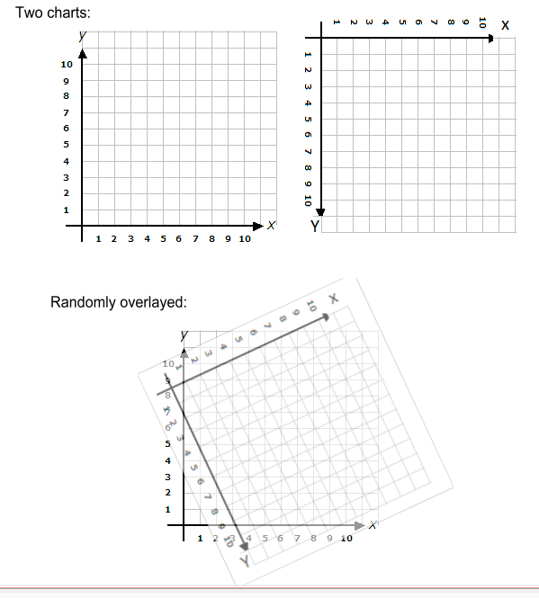
This graphically illustrates the situation.
-
Oct 7th, 2015, 03:20 PM
#13
Re: Maths issue: coordinate systems
I think I have it correct: I was going to draw a similar 'overlay' in Visio. It's been a while since I've done linear algebra, but I think using 3 points will allow you solve the problem.
Let me just restate the actual problem as I understand it: for a given point on one chart, you should be able to punch in those coordinates and it will give you the points on the other chart.
If you use the equations I posted, each point will give you two (2) equations with 6 unknowns. With three (3) data points you will have 6 equations with 6 unknowns (or, two sets of three equations with 3 unknowns each). I think 3 equations with 3 unknowns will give you those unknowns, using simultaneous equation solutions.
This will cover inverted and scaled axes of any amount, as long as they are linear, I believe.
Using your drawing, I came up with these points:
(5,1) == (2.1,9.2)
(2,8) == (2.3,1.6)
(10,7) == (9.1,5.9)
Solving simultaneous equations X0 = M.X1 + N.Y1 + C and Y0 = P.X1 + Q.Y1 + D using the above points we can calculate what M, N, C and P, Q, D are.
Since I'm lazy, I went online to find a simultaneous equation solver and came up with:
M = 0.9018
N = 0.4150
C = -2.8245
and
P = 0.4245
Q = -0.9037
D = 7.9811
So, on the 'correctly' oriented chart, for example, point (8,5) is calculated as follows:
X = 0.9018 x 8 + 0.4150 x 5 - 2.8245 = 6.46 (~6.5)
Y = 0.4245 x 8 - 0.9037 x 5 + 7.9811 = 6.85 (~6.9)
Which, looking at the chart, gives around (6.5,6.8) which I call close enuf for gov't work...
So... this means you need to implement:
* Enter three (3) sets of two (2) points;
* A simultaneous equation solver.
From the above, I think you can also determine:
The offset location of the overlay map; angle of rotation; ratios of X and Y axis scalings, and if the axes are inverted or not. But my brain hurts from all the numbers.
"Ok, my response to that is pending a Google search" - Bucky Katt.
"There are two types of people in the world: Those who can extrapolate from incomplete data sets." - Unk.
"Before you can 'think outside the box' you need to understand where the box is."
-
Oct 7th, 2015, 03:37 PM
#14
Thread Starter
Lively Member
Re: Maths issue: coordinate systems
Hi SJ,
That seems rather impressive (though I admit to not understanding how it works). Your restatement of the desired functionality is correct.
I'm prepared to try to implement this... however, I have zero understanding of a simultaneous equation solver.
Is this the same as matrix calculations?
"This will cover inverted and scaled axes of any amount, as long as they are linear, I believe." <- Perfect solution!
Best regards,
R
Last edited by RyderS; Oct 7th, 2015 at 03:43 PM.
-
Oct 7th, 2015, 03:55 PM
#15
Re: Maths issue: coordinate systems
It has been many, many, years since I've worked with simultaneous equations and matrices, but they are related I believe.
In this case, for the sake of explanation, I went with the premise where the axes are parallel to one another. Given that, taking a single axis with both an offset and a scaling you can use the basic Y=mX+c, or X0=M.X1+C and Y0=P.Y1+D. equation to translate from one axis to another. Given two axes on two graphs, you can use the same equation on each axis.
Still considering that situation, if you have a point on one chart and you move that point, for example, in the X direction, the Y value will not change but the X value will scale according to it's associated linear equation.
Consider a rotated chart, like you have. Consider the same point moving along the X axis. Obviously the associated X value will linearly change, but the Y value will also linearly change. Thus by empirically examining the effect of a point on one chart, we can deduce that the relationship between a point in the X axis on one chart changes both the X and Y coordinates of another in a linear fashion. hence X0=M.X1+N.Y1+C and Y1=P.X1+Q.Y1+D.
The key here, I think, is to visualize what happens to the coordinates on one chart when you modify a point on the other chart.
"Ok, my response to that is pending a Google search" - Bucky Katt.
"There are two types of people in the world: Those who can extrapolate from incomplete data sets." - Unk.
"Before you can 'think outside the box' you need to understand where the box is."
-
Oct 7th, 2015, 04:00 PM
#16
Thread Starter
Lively Member
Re: Maths issue: coordinate systems
I can see how this must be so... but honestly, the maths are entirely above me.
I think I can get to the point where the simultaneous solver is needed... but minus that part, this is short of working.
Thanks for your kind help,
R
-
Oct 7th, 2015, 04:28 PM
#17
Re: Maths issue: coordinate systems
Perhaps the math I used in the other thread post#8 is easier to understand.
The main question is, is it correct?
I'll leave it to you to try some test cases. It seems a bit too simple to work correctly.
-
Oct 7th, 2015, 06:36 PM
#18
Thread Starter
Lively Member
Re: Maths issue: coordinate systems
Hi passel,
Thank you, but sorry, the math in that thread did not work.
R
-
Oct 7th, 2015, 06:46 PM
#19
Re: Maths issue: coordinate systems
I wrote a quick test program to verify the math, and the math turned out to be garbage (which I kind of realized the more I thought about what it was doing).
The test code was easy because it doesn't need to know the math. It draws the two lines and allows you to visually move and rotate the second line with the mouse to lay one over the other. Thus, you've empirically found the "answer" of what Translation and rotation values to apply to a matrix to transform from one coordinate system to the other. See the other thread (linked in my previous post) if you want to run the short and simple test code.
-
Oct 7th, 2015, 07:33 PM
#20
Thread Starter
Lively Member
Re: Maths issue: coordinate systems
Originally Posted by SJWhiteley
Since I'm lazy, I went online to find a simultaneous equation solver ...
Hi SJ...
Can you tell me what on-line calculator you used? I can't seem to find any that appear suitable.
Thank you!
R
-
Oct 7th, 2015, 07:35 PM
#21
Thread Starter
Lively Member
Re: Maths issue: coordinate systems
Last edited by RyderS; Oct 7th, 2015 at 07:36 PM.
Reason: duplication
-
Oct 8th, 2015, 04:56 AM
#22
Re: Maths issue: coordinate systems
I'm still not convinced this isn't a question of code design rather than a mathematical problem. The work of transforming a collection of data points from one coordinate system to another can be done by using the TransformPoints method of the System.Drawing.Drawing2D.Matrix.
Here is a quick sketch of the kind of code I have in mind, based on the illustration in post #12. Assumed: a form (Form1) with a picture box (PictureBox1) and a button (Button1) for testing.
vb.net Code:
Imports System.Drawing.Drawing2D Public Class Form1 'Function to transform points from Cartesian coordinates to rotated, flipped coordinates. Private Function GetTransformedPoints(ByVal data() As PointF, rotation As Integer, centre As PointF, flipY As Boolean) As PointF() Dim mtx As Matrix If flipY Then 'matrix to flip the Y axis mtx = New Matrix(1, 0, 0, -1, 0, 0) Else 'default matrix mtx = New Matrix End If 'rotate the matrix mtx.RotateAt(rotation, centre) 'get the positions of the transformed points: mtx.TransformPoints(data) Return data End Function 'test the function: Private Sub Button1_Click(sender As Object, e As EventArgs) Handles Button1.Click Dim data() As PointF = {New Point(10, 10), New Point(200, 50), New Point(6, 150)} Dim rotation As Integer = 27 Dim centre As New PointF(PictureBox1.ClientSize.Width / 2.0F, PictureBox1.ClientSize.Height / 2.0F) Dim result(data.Count - 1) As PointF Array.Copy(data, result, data.Count) result = GetTransformedPoints(result, rotation, centre, True) For i As Integer = 0 To data.Count - 1 Console.Write(data(i).ToString & " is transformed to ") Console.WriteLine(result(i).ToString) Next Console.WriteLine() End Sub End Class
I haven't tested the above code and it may contain errors; it's just to give an idea of the coding possibilities. As you can see there is no serious mathematics involved. And it doesn't do any drawing, which isn't necessary for just getting the transformed points.
In practice you would probably declare the matrix at form level and use it to draw a transformed graph with the Graphics.Transform method. Transformation in the opposite direction is done by inverting the matrix (Matrix.Invert method); that can be useful for hit testing a point clicked on a view of the transformed graph.
BB
-
Oct 8th, 2015, 06:22 AM
#23
Re: Maths issue: coordinate systems
boop boops, you are correct with the matrix transforms, and it may be better than using simultaneous equations - simultaneous equations and matrices are closely linked, however. The problem is going to be to determine what transform to apply, since the scaling of each axis is (ultimately) unknown as well as the rotation. I think that's really the point. If, from calibration, the matrix and angle can be determined, then the simultaneous equation solver is not needed, and a matrix transform can be applied.
The question would be, from 3 (or more, or less) known intersects, how would the angle and matrix be determined? I think it could be done using geometry, but may still be in the situation of solving simultaneous equations to get the matrix coefficients.
The equation solver I used was here: http://equationsolver.intemodino.com...equations.html. It's a java applet.
It appears creating a simultaneous equation solver in code is NOT a trivial task. So, while I may have said the math is trivial, it appears the solution is far from it; and, of course, if one is not so good at math, then the math is far from trivial, also  But, in this case, once the sequence of math is determined to solve the coefficients, then it would be a case of replicating that in code. But, in this case, once the sequence of math is determined to solve the coefficients, then it would be a case of replicating that in code.
I'd be interested to know the alternative solution using matrices; and determining the coefficients.
"Ok, my response to that is pending a Google search" - Bucky Katt.
"There are two types of people in the world: Those who can extrapolate from incomplete data sets." - Unk.
"Before you can 'think outside the box' you need to understand where the box is."
-
Oct 8th, 2015, 11:06 AM
#24
Re: Maths issue: coordinate systems
Well, the code I posted yesterday in the other thread worked, but required the user to visually do the rotation and lining up given the two matching points from each chart.
Trying to align it by eye using the mouse is a bit of a challenge, and you are adjusting several parameters that interact, offsets, rotations, and scale.
So, I got it close, and then was tweaking values by hand in the debugger immediate window, and checking the known points to see if they were reported reliably. I assumed if you got the offset values, scaling and rotation correct, then the two lines should line up exactly and you would only see one color (the one on "top"), with out any bleeding around the edges.
Since I was just tweaking the numbers and checking an input point's conversion through the matrix to its output to see if it matched the known value, I knew that could be automated.
So, I added code to just do a brute force calibration based on the two line segments out to within .0001 degrees of angle and .0001 units of offset and .0001 resolution of scaling, by simply looping and adjusting the values from one side of the target, and stopping when it crossed the target.
The code needs to be expanded to actually handle the Inverted Y case, and determine which direction you need to rotate, and which direction to scale, before being considered a full example.
The code is basically just written knowing which side (direction) you need to go, so just moves in the correct direction by the minimal step until it crosses a target value. Plenty of areas to optimize and fill in to make it a useful tool.
As boops boops says, once the calibration is done, and the matrix set up, you can used it to transform points, so the GUI drawing part is not necessary, but was left in since I just added the extra routines to do the automatic calibration late last night.
I don't believe I'm planning on honing this to make it a usable tool.
I changed the drawing first, to put crosshair size markings at the endpoints (2 pixels wide to match the cursor cross icon), so you know when the cursor is exactly on the end points (the center of the cross goes dark, both horizontally and vertically).
When over those points you can verify that the input values from the one chart, give you the expected output values from the other chart.
The input line originally given (Y axis is not inverted in either chart) was (9, 7) to (41, 25).
The input line from the second chart that overlays the first chart was (6.5, 11.2) TO (43.2, 21.4).
So, when you put the cursor over the first point, you expect to see ptIn: on the titlebar showing (9, 7) and ptOut: showing (6.5, 11.2). Similarly, the second set of numbers for the second point of the line segment.
It turns out the second chart has to be scaled by about .9638.
The commented out presets of the values in the declaration were from my eyeballing the alignment, which I wanted to save.
Once I added the autocalibration routines, I commented them out, so the calibration had to work from scratch.
Again, this only solves for the case where the second line is longer, and at a shallower angle compared to the first line because of the numbers given above fell into that category. The other possible combinations of orientation and Inverted Y axis would need to be added to be fully useful.
There is probably a mathematical way to determine the required angle, scaling and offsets to set up the matrix, rather than this brute force looping and testing.
Event the "brute force" could be made more efficient by doing a binary search for the values down to some set resolution, rather than a linear small increment loop.
I'm leaving that to the implementers.
The crosses are aligned to the X,Y axis of the two charts (the original in yellow, the second in Red), and the line doesn't happen to be aligned with either X,Y axis in either chart.
The code calibrates the angle first, since that is not dependent on line lengths, then once the lines are parallel, it calibrates the scale so the lines are the same length, then it simply computes the X and Y offsets (at the bottom of the Scale Calibration routine) based on putting the first point of each line on top of one another.
Code:
Public Class Form1

  Private Ang As Single ' = 13.8055
  Private Scl As Single = 1 ' 0.9645
  Private Xoff As Single '= 5.49
  Private Yoff As Single '= -4.98
  Private mInv As New Drawing2D.Matrix
  Private pt1, pt2, pt3, pt4 As PointF

  Private Sub Form1_Load(sender As System.Object, e As System.EventArgs) Handles MyBase.Load
    DoubleBuffered = True
    Me.Cursor = Cursors.Cross
    Me.BackColor = Color.Black
    pt1 = New PointF(9, 7) : pt2 = New PointF(41, 25)
    pt3 = New PointF(6.5, 11.2) : pt4 = New PointF(43.2, 21.4)
    calibrateang()
    CalibrateScale()
  End Sub

  Private Sub CalibrateScale()
    Dim dx1 As Single = pt2.X - pt1.X
    Dim dx2 As Single
    Dim dy1 As Single = pt2.Y - pt1.Y
    Dim dy2 As Single
    Dim mtx As New Drawing2D.Matrix
    Dim nPts(1) As PointF
    Dim d1 As Double = Math.Sqrt((dx1 * dx1) + (dy1 * dy1))
    Dim d2 As Double
    mtx.Rotate(Ang)
    nPts(0) = pt3 : nPts(1) = pt4
    mtx.TransformPoints(nPts)
    dx2 = nPts(1).X - nPts(0).X
    dy2 = nPts(1).Y - nPts(0).Y
    d2 = Math.Sqrt((dx2 * dx2) + (dy2 * dy2))
    Do While d2 > d1
      mtx.Reset()
      mtx.Rotate(Ang)
      Scl -= 0.0001F
      mtx.Scale(Scl, Scl)
      nPts(0) = pt3 : nPts(1) = pt4
      mtx.TransformPoints(nPts)
      dx2 = nPts(1).X - nPts(0).X
      dy2 = nPts(1).Y - nPts(0).Y
      d2 = Math.Sqrt((dx2 * dx2) + (dy2 * dy2))
    Loop
    Xoff = pt1.X - nPts(0).X
    Yoff = pt1.Y - nPts(0).Y
  End Sub

  Private Sub calibrateang()
    Dim dx1 As Single = pt2.X - pt1.X
    Dim dx2 As Single = pt4.X - pt3.X
    Dim dy1 As Single = pt2.Y - pt1.Y
    Dim dy2 As Single = pt4.Y - pt3.Y
    Dim dr1 As Single = dx1 / dy1
    Dim dr2 As Single = dx2 / dy2
    Dim nPts(1) As PointF
    '  Ang = Ang - 1
    Dim mtx As New Drawing2D.Matrix

    If dr1 < dr2 Then
      Do While dr1 < dr2
        ang += 0.0001F
        mtx.Reset()
        mtx.Rotate(ang)
        nPts(0) = pt3 : nPts(1) = pt4
        mtx.TransformPoints(nPts)
        dx2 = nPts(1).X - nPts(0).X
        dy2 = nPts(1).Y - nPts(0).Y
        dr2 = dx2 / dy2
      Loop
    End If
  End Sub

  Private Sub Form1_MouseMove(sender As Object, e As System.Windows.Forms.MouseEventArgs) Handles Me.MouseMove
    Static lPos As Point
    If e.Button = Windows.Forms.MouseButtons.Left Then
      Xoff += (e.X - lPos.X) / 100.0F
      Yoff += (e.Y - lPos.Y) / 100.0F
      Refresh()
    ElseIf e.Button = Windows.Forms.MouseButtons.Right Then
      If My.Computer.Keyboard.ShiftKeyDown Then
        Scl += (e.X - lPos.X) / 1000.0F
      Else
        Ang += (e.X - lPos.X) / 100.0F
      End If

      Refresh()
      End If
      lPos = e.Location
      Dim sPnt As PointF = New PointF(lPos.X / 10.0F, lPos.Y / 10.0F)
      Dim nPnt() As PointF = {New PointF(lPos.X, lPos.Y)}
      mInv.TransformPoints(nPnt)

    Me.Text = String.Format("Xoff: {0}, Yoff: {1}, Ang: {2}, Scale: {6}, PtIn: {3} PtOut: (X={4}, Y={5})",
                            Xoff.ToString("F4"), Yoff.ToString("F4"), Ang.ToString("F4"),
                            sPnt.ToString, nPnt(0).X.ToString("F2"), nPnt(0).Y.ToString("F2"), Scl.ToString("F4"))
  End Sub

  Private Sub Form1_Paint(sender As Object, e As System.Windows.Forms.PaintEventArgs) Handles Me.Paint
    Dim g As Graphics = e.Graphics

    Using bPen As New Pen(Brushes.Yellow, 0)
      Using rPen As New Pen(Brushes.Red, 0)
        Using b1Pen As New Pen(Brushes.Yellow, 0.2)
          Using r1Pen As New Pen(Brushes.Red, 0.2)

            Const r As Drawing2D.LineCap = Drawing2D.LineCap.Round
            bPen.SetLineCap(r, r, 0)
            rPen.SetLineCap(r, r, 0)
            g.ScaleTransform(10, 10)
            g.DrawLine(bPen, 9, 7, 41, 25)
            g.DrawLine(b1Pen, 9, 4, 9, 10) : g.DrawLine(b1Pen, 6, 7, 12, 7) 'draw a cross hair
            g.DrawLine(b1Pen, 41, 22, 41, 28) : g.DrawLine(b1Pen, 38, 25, 44, 25) 'draw a cross hair

            g.TranslateTransform(Xoff, Yoff)
            g.RotateTransform(Ang)
            g.ScaleTransform(Scl, Scl)
            mInv = g.Transform.Clone
            mInv.Invert()
            g.DrawLine(rPen, 6.5, 11.2, 43.2, 21.4)

            g.DrawLine(r1Pen, 6.5, 8.2, 6.5, 14.2) : g.DrawLine(r1Pen, 3.5, 11.2, 9.5, 11.2) 'draw a cross hair
            g.DrawLine(r1Pen, 43.2, 18.4, 43.2, 24.4) : g.DrawLine(r1Pen, 40.2, 21.4, 46.2, 21.4) 'draw a cross hair
          End Using
        End Using
      End Using
    End Using

  End Sub
End Class
Last edited by passel; Oct 8th, 2015 at 11:32 AM.
-
Oct 8th, 2015, 11:18 AM
#25
Re: Maths issue: coordinate systems
Okay, I couldn't let this puzzle get away from me.
You don't need any kind of library or code to solve simultaneous equations, since they are known, simply perform the calculations by hand to determine the formulae for each of the constants.
I came up with this code, which results in the same values using an online calculator.
Once the constants are known, you can type in any point, using the basic two equations, to get a point on the second chart:
Code:
Public Class Form1

	Private P0 As PointF
	Private P1 As PointF
	Private P2 As PointF

	Private Pa As PointF
	Private Pb As PointF
	Private Pc As PointF

	Private N As Double
	Private M As Double
	Private C As Double
	Private P As Double
	Private Q As Double
	Private D As Double

	Private Sub Form1_Load(sender As System.Object, e As System.EventArgs) Handles MyBase.Load
		'
		' Set the CALIBRATION points
		'
		' Source points
		Pa = New PointF(5, 1)
		Pb = New PointF(2, 8)
		Pc = New PointF(10, 7)
		' Target Points
		P0 = New PointF(2.1, 9.2)
		P1 = New PointF(2.3, 1.6)
		P2 = New PointF(9.1, 5.9)
	End Sub

	Private Sub Button1_Click(sender As System.Object, e As System.EventArgs) Handles Button1.Click
		Call SolveConstants()
	End Sub

	Private Sub SolveConstants()
		' M, N, C
		' =======
		' (1): P0x = M.Pax + N.Pay + C
		' (2): P1x = M.Pbx + N.Pby + C
		' (3): P2x = M.Pcx + N.Pcy + C
		'
		' Solving for N:
		'
		' (4): from (1): C = P0x - M.Pax - N.Pay
		'
		' from (2) and (4):      P1x = M.Pbx + N.Pby + P0x - M.Pax - N.Pay
		'                            = M.(Pbx - Pax) + N.(Pby - Pay) + P0x
		'              M.(Pbx - Pax) = P1x - N.(Pby - Pay) - P0x
		' (6):                     M = (P1x - N.(Pby - Pay) - P0x) / (Pbx - Pax)
		'
		' using (4) and (3):     P2x = M.Pcx + N.Pcy + P0x - M.Pax - N.Pay
		'                            = M.(Pcx - Pax) + N.(Pcy - Pay) + P0x
		' using (6):                 = (Pcx - Pax).(P1x - N.(Pby - Pay) - P0x) / (Pbx - Pax) + N.(Pcy - Pay) + P0x
		'            P2x.(Pbx - Pax) = (Pcx - Pax).(P1x - N.(Pby - Pay) - P0x) + N.(Pcy - Pay).(Pbx - Pax) + P0x.(Pbx - Pax)
		'                            = P1x.(Pcx - Pax) - N.(Pby - Pay).(Pcx - Pax) - P0x.(Pcx - Pax) + N.(Pcy - Pay).(Pbx - Pax) + P0x.(Pbx - Pax)
		'                            = P1x.(Pcx - Pax) + N.((Pcy - Pay).(Pbx - Pax) - (Pby - Pay).(Pcx - Pax)) - P0x.(Pcx - Pax) + P0x.(Pbx - Pax)
		' (7):                     N = (P2x.(Pbx - Pax) - P1x.(Pcx - Pax) + P0x.(Pcx - Pax) - P0x.(Pbx - Pax)) / ((Pcy - Pay).(Pbx - Pax) - (Pby - Pay).(Pcx - Pax))
		'
		' Using (7)
		N = (P2.X * (Pb.X - Pa.X) - P1.X * (Pc.X - Pa.X) + P0.X * (Pc.X - Pa.X) - P0.X * (Pb.X - Pa.X)) / ((Pc.Y - Pa.Y) * (Pb.X - Pa.X) - (Pb.Y - Pa.Y) * (Pc.X - Pa.X))
		' using the results of (7) and putting in (6)
		M = (P1.X - N * (Pb.Y - Pa.Y) - P0.X) / (Pb.X - Pa.X)
		' Putting in (4):
		C = P0.X - M * Pa.X - N * Pa.Y

		Debug.WriteLine("N=" & N)
		Debug.WriteLine("M=" & M)
		Debug.WriteLine("C=" & C)
		'
		' Similarly for P, Q and D
		Q = (P2.Y * (Pb.X - Pa.X) - P1.Y * (Pc.X - Pa.X) + P0.Y * (Pc.X - Pa.X) - P0.Y * (Pb.X - Pa.X)) / ((Pc.Y - Pa.Y) * (Pb.X - Pa.X) - (Pb.Y - Pa.Y) * (Pc.X - Pa.X))
		P = (P1.Y - Q * (Pb.Y - Pa.Y) - P0.Y) / (Pb.X - Pa.X)
		D = P0.Y - P * Pa.X - Q * Pa.Y
		'
		Debug.WriteLine("P=" & P)
		Debug.WriteLine("Q=" & Q)
		Debug.WriteLine("D=" & D)
		'
	End Sub

End Class
(Note that the code wraps ugly: the equations for N and Q are quite long, as well as the comments demonstrating how to solve for simultaneous equations).
"Ok, my response to that is pending a Google search" - Bucky Katt.
"There are two types of people in the world: Those who can extrapolate from incomplete data sets." - Unk.
"Before you can 'think outside the box' you need to understand where the box is."
-
Oct 8th, 2015, 11:47 AM
#26
Re: Maths issue: coordinate systems
I've added some comments to the code to explain the more involved parts.
If you pulled the two Calibration routines, and a bit of the code, and put the bit at the bottom of the MouseMove routine into a sub or function (without the /10.0F of course), you would have a tool that you could put the initial points in, calibrate, then put in other points to convert and display.
Just need to complete the missing cases in the calibration, and add the Y inversion capability, probably similar to what boops boops has shown.
May want to optimize the calibration, although even brute force calibration doesn't take too long (but here the charts are only about 14 degrees out of phase (so about 140,000 loops through the angle calibration), it would take longer the more out of phase the two charts were.
So, more comments for those who want to do more than just run the code.
Code:
Public Class Form1

  Private Ang As Single ' = 13.8055
  Private Scl As Single = 1 ' 0.9645
  Private Xoff As Single '= 5.49
  Private Yoff As Single '= -4.98
  Private mInv As New Drawing2D.Matrix
  Private pt1, pt2, pt3, pt4 As PointF

  Private Sub Form1_Load(sender As System.Object, e As System.EventArgs) Handles MyBase.Load
    DoubleBuffered = True
    Me.Cursor = Cursors.Cross
    Me.BackColor = Color.Black
    pt1 = New PointF(9, 7) : pt2 = New PointF(41, 25)
    pt3 = New PointF(6.5, 11.2) : pt4 = New PointF(43.2, 21.4)
    calibrateang()
    CalibrateScale()
  End Sub

  Private Sub CalibrateScale()
    Dim dx1 As Single = pt2.X - pt1.X
    Dim dx2 As Single
    Dim dy1 As Single = pt2.Y - pt1.Y
    Dim dy2 As Single
    Dim mtx As New Drawing2D.Matrix
    Dim nPts(1) As PointF
    Dim d1 As Double = Math.Sqrt((dx1 * dx1) + (dy1 * dy1))    'Compute the length of chart1's line
    Dim d2 As Double

    mtx.Rotate(Ang)                                            'Apply our computed angle to the matrix
    nPts(0) = pt3 : nPts(1) = pt4                              'Put our line2 coordinates in the array
    mtx.TransformPoints(nPts)                                  'Have the matrix transform them to chart1's coordinates
    dx2 = nPts(1).X - nPts(0).X
    dy2 = nPts(1).Y - nPts(0).Y
    d2 = Math.Sqrt((dx2 * dx2) + (dy2 * dy2))                  'Compute the length of chart2's line in this coordinate system
    Do While d2 > d1                                           'If the line is long (didn't write the other case)
      mtx.Reset()                                              '  Reset the matrix (to avoid accumlation)
      mtx.Rotate(Ang)                                          '  Repeat the above steps to transform line2's coordinates
      Scl -= 0.0001F                                           '  but reducing the scale (shortening the line) each cycle
      mtx.Scale(Scl, Scl)
      nPts(0) = pt3 : nPts(1) = pt4
      mtx.TransformPoints(nPts)
      dx2 = nPts(1).X - nPts(0).X
      dy2 = nPts(1).Y - nPts(0).Y
      d2 = Math.Sqrt((dx2 * dx2) + (dy2 * dy2))
    Loop                                                       'Loop is exited when length = or < by .0001 units
    Xoff = pt1.X - nPts(0).X                                   'Now simply compute how far the first point of the second line
    Yoff = pt1.Y - nPts(0).Y                                   'needs to be moved to align with the first line
  End Sub

  Private Sub calibrateang()
    Dim dx1 As Single = pt2.X - pt1.X      'Delta X between chart1's line
    Dim dx2 As Single = pt4.X - pt3.X      'Delta X between chart2's line
    Dim dy1 As Single = pt2.Y - pt1.Y      'Delta Y chart1
    Dim dy2 As Single = pt4.Y - pt3.Y      'Delta Y chart2
    Dim dr1 As Single = dx1 / dy1          'Essentially the slope of line 1
    Dim dr2 As Single = dx2 / dy2          ' slope of line 2
    Dim nPts(1) As PointF                  'Point array used for Matrix transformation
    Dim mtx As New Drawing2D.Matrix        'A matrix to work with

    If dr1 < dr2 Then                      'Didn't code the other case
      Do While dr1 < dr2                   '  While we are less than the target
        Ang += 0.0001F                     '    Increment the Angle by a small amount
        mtx.Reset()                        '    Reset our Matrix (would accumlate angle otherwise)
        mtx.Rotate(Ang)                    '    Rotate by the current Angle amount
        nPts(0) = pt3 : nPts(1) = pt4      '    Put our second charts line coordinates in the array
        mtx.TransformPoints(nPts)          '    Have the matrix rotate the points by the angle
        dx2 = nPts(1).X - nPts(0).X        '    Compute deltaX for the rotated line
        dy2 = nPts(1).Y - nPts(0).Y        '    DeltaY
        dr2 = dx2 / dy2                    '    Slope of the rotated line
      Loop                                 '  Loop back up to see if slope is now equal or > than Line1
    End If                                 'Loop exits when the angles are within .0001 of each other
  End Sub

  Private Sub Form1_MouseMove(sender As Object, e As System.Windows.Forms.MouseEventArgs) Handles Me.MouseMove
    Static lPos As Point
    If e.Button = Windows.Forms.MouseButtons.Left Then            'If left button is down
      Xoff += (e.X - lPos.X) / 100.0F                             '  move line2 (by adjusting offsets to the matrix)
      Yoff += (e.Y - lPos.Y) / 100.0F
      Refresh()

    ElseIf e.Button = Windows.Forms.MouseButtons.Right Then       'Else if right button is down
      If My.Computer.Keyboard.ShiftKeyDown Then                   '  If shiftkey is also down
        Scl += (e.X - lPos.X) / 1000.0F                           '     adjust the scale
      Else                                                        '  otherwise
        Ang += (e.X - lPos.X) / 100.0F                            '     adjust the rotation
      End If

      Refresh()
    End If

    'Get the mouse position and use the inverted Matrix to convert from Chart1's coordinates, to Chart2's coordinates
    'We've scaled the image up 10x to make it easier to manipulate, so have to devide mouse coordinate by 10
    'to get chart1's coordinates.
    'Show the various parameter settings, and the Chart1 and Chart2 coordinates on the titlebar
    lPos = e.Location
    Dim sPnt As PointF = New PointF(lPos.X / 10.0F, lPos.Y / 10.0F)
    Dim nPnt() As PointF = {New PointF(lPos.X, lPos.Y)}
    mInv.TransformPoints(nPnt)

    Me.Text = String.Format("Xoff: {0}, Yoff: {1}, Ang: {2}, Scale: {6}, PtIn: {3} PtOut: (X={4}, Y={5})",
                            Xoff.ToString("F4"), Yoff.ToString("F4"), Ang.ToString("F4"),
                            sPnt.ToString, nPnt(0).X.ToString("F2"), nPnt(0).Y.ToString("F2"), Scl.ToString("F4"))
  End Sub

  Private Sub Form1_Paint(sender As Object, e As System.Windows.Forms.PaintEventArgs) Handles Me.Paint
    Dim g As Graphics = e.Graphics

    Using bPen As New Pen(Brushes.Yellow, 0)
      Using rPen As New Pen(Brushes.Red, 0)
        Using b1Pen As New Pen(Brushes.Yellow, 0.2)
          Using r1Pen As New Pen(Brushes.Red, 0.2)

            Const r As Drawing2D.LineCap = Drawing2D.LineCap.Round
            bPen.SetLineCap(r, r, 0)
            rPen.SetLineCap(r, r, 0)
            g.ScaleTransform(10, 10)
            g.DrawLine(bPen, 9, 7, 41, 25)
            g.DrawLine(b1Pen, 9, 4, 9, 10) : g.DrawLine(b1Pen, 6, 7, 12, 7) 'draw a cross hair
            g.DrawLine(b1Pen, 41, 22, 41, 28) : g.DrawLine(b1Pen, 38, 25, 44, 25) 'draw a cross hair

            g.TranslateTransform(Xoff, Yoff)
            g.RotateTransform(Ang)
            g.ScaleTransform(Scl, Scl)
            mInv = g.Transform.Clone
            mInv.Invert()
            g.DrawLine(rPen, 6.5, 11.2, 43.2, 21.4)

            g.DrawLine(r1Pen, 6.5, 8.2, 6.5, 14.2) : g.DrawLine(r1Pen, 3.5, 11.2, 9.5, 11.2) 'draw a cross hair
            g.DrawLine(r1Pen, 43.2, 18.4, 43.2, 24.4) : g.DrawLine(r1Pen, 40.2, 21.4, 46.2, 21.4) 'draw a cross hair
          End Using
        End Using
      End Using
    End Using

  End Sub
End Class
-
Oct 8th, 2015, 12:20 PM
#27
Re: Maths issue: coordinate systems
In my previous post I didn't look at the question of calibration. I just wanted to illustrate that the Drawing2D.Matrix methods aren't particularly frightening. As long as there's no scaling involved only two calibration points are needed and relatively simple geometry ideas could be used. For example, get the slope of each pair of points using Math.Atan2, subtract the two slopes to get the rotation angle, apply it to a matrix with Matrix.Rotate, and use Matrix.TransformPoints to find where the rotated points end up. Then compare the X and Y of corresponding points to get the offset (each pair of points should give the same result if there is no scaling).
Once scaling is also involved, you need at least three calibration points and it's rather more complex. I'd like to pose an alternative to SWJ's simultaneous equation approach and Passel's "brute force" approach. The 3 points on each chart forms a triangle. It must be possible to find the Rotation, Scale and Translation to be applied to a Matrix by comparing the two triangles. For that purpose I like the look of the matrix method posted in this StackOverflow thread.
BB
-
Oct 8th, 2015, 01:28 PM
#28
Thread Starter
Lively Member
Re: Maths issue: coordinate systems
Originally Posted by SJWhiteley
Okay, I couldn't let this puzzle get away from me.
Holy Smokes SJ!
I am TRULY humbled... and appreciative. I've implemented it as a test, and it seems to work!
I'm so appreciative of all members that helped with this... SJ, passel, boops, it turned out to be quite an endeavor! Heroes all.
Let me share with you what's been accomplished... (knowing the result of hard effort is sometimes a reward?)
Image a microscope with a motorized X, Y stage for viewing. Imagine now that on this stage is a semiconductor wafer, which has on it thousands and thousands of individual integrated circuits...
The circuits can be known by their XY position... in a unique coordinate system.
And the motorized stage position is known (on it's different coordinate system), because it "talks" to a PC.
The actual location and theta of the wafer as it sits on the viewing stage is unknown.
By looking at three known ICs in the microscope, and asking the stage where it is, three calibration points are generated.
I can now drive the stage to view any other device on the IC, and by asking the stage where it is, I can know which device is being looked at! (which is important, because they all look identical)
I've yet to implement it on the scope of course, and there's more work to remap coordinates to ANOTHER mapping system of "chip ID's"... which I guarantee you won't be fun, but the foundation exists to make it possible.
My sincerest thanks.
-
Oct 8th, 2015, 02:23 PM
#29
Re: Maths issue: coordinate systems
Originally Posted by boops boops
... For example, get the slope of each pair of points using Math.Atan2, subtract the two slopes to get the rotation angle, apply it to a matrix with Matrix.Rotate, and use Matrix.TransformPoints to find where the rotated points end up...
I did that originally, but the angle didn't work out.
But I was going to show you the example inputs and output, and explain why I though it wasn't working and I recognized that when I redid the Atan2 call today the result of one of the slopes was not the one I remembered from the other day.
I had that all written in a notepad session, but in the end didn't save any of those notes, so can't go back to see where I (obviously) grabbed the wrong number for one of the coordinate X values, and through off my angle (I was getting around 16 degrees when the answer should have been around 14 degrees). Today, I'm getting the expected 13.825... degrees from the Atan2, which is close to what the bruteforce method got.
So, probably because of some simple misread or typo, I went away from Atan2 and onto this tangent (no pun intended).
Now, that that is straightened out, I can return to my original tact.
My assumption is that the coordinate system is square (originally based on the statement at one point that it was millimeters) although the chart underneath can be at a different scale and orientation.
Given that, I don't see the need for three points to determine scale. You have two known points that should represent the same distance, so if you calculate the distance for both in their respective scales, then the ratio between those distances should give you the scale difference between the two.
So, returning to the direct computation method that I started yesterday, then abandoned, the CalibrateScale and CalibrateAngle routines look like this
Code:
  Private Sub calibrateang()
    Dim dx1 As Single = pt2.X - pt1.X      'Delta X between chart1's line
    Dim dx2 As Single = pt4.X - pt3.X      'Delta X between chart2's line
    Dim dy1 As Single = pt2.Y - pt1.Y      'Delta Y chart1
    Dim dy2 As Single = pt4.Y - pt3.Y      'Delta Y chart2

    Ang = CSng((Math.Atan2(dy1, dx1) - Math.Atan2(dy2, dx2)) * 180 / Math.PI)
  End Sub

  Private Sub CalibrateScale()
    Dim dx1 As Single = pt2.X - pt1.X
    Dim dx2 As Single = pt4.X - pt3.X
    Dim dy1 As Single = pt2.Y - pt1.Y
    Dim dy2 As Single = pt4.Y - pt3.Y
    Dim mtx As New Drawing2D.Matrix
    Dim nPts(1) As PointF
    Dim d1 As Double = Math.Sqrt((dx1 * dx1) + (dy1 * dy1))    'Compute the length of chart1's line
    Dim d2 As Double = Math.Sqrt((dx2 * dx2) + (dy2 * dy2))

    Scl = CSng(d1 / d2)                                        'The scale is the ratio of distance1 to distance2

    mtx.Rotate(Ang)                                            'Apply our computed angle to the matrix
    mtx.Scale(Scl, Scl)                                        'Apply our scale
    nPts(0) = pt3 : nPts(1) = pt4                              'Put our line2 coordinates in the array
    mtx.TransformPoints(nPts)                                  'Have the matrix transform them to chart1's coordinates

    Xoff = pt1.X - nPts(0).X                                   'Now simply compute how far the first point of the second line
    Yoff = pt1.Y - nPts(0).Y                                   'needs to be moved to align with the first line
  End Sub
I guess I needed a second pair of eyes yesterday, or at least the confidence to know that Atan2 between the two coordinate systems should work, and if not, I must have made a mistake somewhere. (I thought I went through it more than once several ways yesterday, but must have made the error copying info to the notepad I used as a scratchpad and kept using the same incorrect value from there).
Last edited by passel; Oct 8th, 2015 at 02:47 PM.
Tags for this Thread
 Posting Permissions
- You may not post new threads
- You may not post replies
- You may not post attachments
- You may not edit your posts
-
Forum Rules
|
Click Here to Expand Forum to Full Width
|


 Reply With Quote

