I have done this routine for dashed lines where the X and Y axis have different scales.
Code:
Private Sub DashedLinePK(obj As Object, XYscale As Single, X1 As Single, Y1 As Single, X2 As Single, Y2 As Single, LineThickness As Integer, LineColour As Long)
Dim DashLength As Single, SkipLength As Single, Incr As Integer, dX As Single, dY As Single, X As Single, Y As Single, Xstart As Single, Ystart As Single, Xend As Single, Yend As Single
Dim VisualLength As Single, i As Integer, CalcLength As Single, AltLength As Single, VisualAngle As Single, CalcAngle As Single

'standarddize the two axis
'XYscale = (25.5 - 17.5) / 750       'ScaleWidth in user units/scalewidth in pixels
dX = X2 - X1
dY = Y2 - Y1
If dX <> 0 Then CalcAngle = Atn(Abs(dY / dX)) Else CalcAngle = Pi / 2
CalcLength = Sqr((dX) ^ 2 + (dY) ^ 2)
VisualLength = CalcLength * XYscale
If X2 - X1 = 0 Then
    VisualAngle = Pi / 2
Else
    If Y2 - Y1 = 0 Then
        VisualAngle = 0
    Else
        VisualAngle = Atn(Abs(Y2 - Y1) * XYscale / Abs(X2 - X1))
    End If
End If

If MyFunction = 1 Then
    DashLength = 0.0000002 + 0.08 * Sin(VisualAngle)
    SkipLength = 0.00000006 + 0.02 * Sin(VisualAngle)
End If

If MyFunction = 6 Then
    DashLength = 50 - 20 * Sin(VisualAngle)
    SkipLength = 25 - 20 * Sin(VisualAngle)
End If


Incr = VisualLength / (DashLength + SkipLength)
'If Incr = 0 Then
'    DashLength = CalcLength * 0.7
'    SkipLength = CalcLength * 0.3
'Else
'    DashLength = 0.1 + CalcLength * 0.7 / Incr
'    SkipLength = 0.1 + CalcLength * 0.3 / Incr
'End If

'Debug.Print BeginNode, EndNode, , FormatNumber(VisualAngle * 180 / Pi, 0), FormatNumber(DashLength, 4)
X = X1
Y = Y1
obj.DrawWidth = 2
For i = 1 To Incr
    Xstart = X1 + (i - 1) * dX / Incr
    Ystart = Y1 + (i - 1) * dY / Incr
    Xend = Xstart + (dX * DashLength / (DashLength + SkipLength)) / Incr
    Yend = Ystart + (dY * DashLength / (DashLength + SkipLength)) / Incr
    obj.Line (Xstart, Ystart)-(Xend, Yend), LineColour
Next i
Exit Sub

End Sub
However, it does not work perfectly as there is some discrepency. This routine allows for a linear interpolation of the lengths, whilst it should be a quadratic interpolation.
I am sure one of you guys out there have solved this rpblem as it is a general one, one often gets.
Private Sub Form_Resize()
    Dim LOGBRUSH As LOGBRUSH
    Dim DashStyles() As Long
    Dim hPen As Long
    Dim hPenPrev As Long

    If WindowState <> vbMinimized Then
        AutoRedraw = True
        Cls
        'A solid line:
        With LOGBRUSH
            .lbStyle = BS_SOLID
            .lbColor = vbYellow
        End With
        hPen = ExtCreatePen(PS_GEOMETRIC Or PS_ENDCAP_FLAT, _
                            5, _
                            LOGBRUSH)
        hPenPrev = SelectObject(hDC, hPen)
        Line (ScaleX(40, vbPixels), ScaleY(40, vbPixels)) _
            -(ScaleWidth - ScaleX(40, vbPixels), ScaleHeight - ScaleY(40, vbPixels))
        SelectObject hDC, hPenPrev
        DeleteObject hPen

        'A custom dashed line:
        With LOGBRUSH
            .lbStyle = BS_SOLID
            .lbColor = vbGreen
        End With
        ReDim DashStyles(3)
        DashStyles(0) = 30
        DashStyles(1) = 5
        DashStyles(2) = 5
        DashStyles(3) = 15
        hPen = ExtCreatePen(PS_GEOMETRIC Or PS_ENDCAP_FLAT Or PS_USERSTYLE, _
                            5, _
                            LOGBRUSH, _
                            UBound(DashStyles) + 1, _
                            VarPtr(DashStyles(0)))
        hPenPrev = SelectObject(hDC, hPen)
        Line (ScaleX(60, vbPixels), ScaleY(40, vbPixels)) _
            -(ScaleWidth - ScaleX(20, vbPixels), ScaleHeight - ScaleY(40, vbPixels))
        SelectObject hDC, hPenPrev
        DeleteObject hPen
        AutoRedraw = False
    End If
End Sub
Because it is in the Resize event here, you can resize the Form, maximize it, etc. to see the drawing speed.
Is there something about your "X and Y scales" that I missed?
Thanks so much for the attached project - excellent as always and appreciated.
I will implement it, which may take a few days, and let you know.
Is there something about your "X and Y scales" that I missed?
The question of scales is a general one, and in my application applies to degrees of latitude and longitude.
This is especially so at high latitudes where the distance between degrees of latitude and degrees of longitude differ significantly, and changes all the time as one goes more south or more north.
When I have a map on a picturebox, the same number of latitudinal degrees have very different distances than the same number of longitudinal degees.
The effect of this is that when I draw a line for a legend (in this case a valve on a pipeline) from X1,Y1 to X2,Y2, the length of the line will change as the angle of the line changes. A vertical line will be much longer than the horizontal line with lengths in between depending on the angle of the line.
The vertical valves do not have the same size as the horizontal or diagonal ones. I do need these valves to have the same size, regardless of the angle it makes.
I do think that your attached project caters for this, and will check on my application.
P.S. The routine has an hPenPrev with an hDC reference, and left as per your code, it draws a line on the whole form except my picturebox. How do I set it to draw on my picturebox only?
A pen gets assigned to a device context. A PictureBox is a very "heavy" control, nearly as fat as another Form. It has its own DC.
To use a pen you must "select it" into the DC you want to draw on. When you do this, you need to grab the previous pen and restore it back to the DC once you are done.
In my example I wrote the two line-drawing operations as "atomic" in the sense you could delete all of the code for either line without breaking anything. But you could also write it so it only grabbed the original pen for the first new pen, and then restore that once: when all done drawing. Both created pens still need to be deleted after use. As it says in the documentation:
An application should always replace a new object with the original, default object after it has finished drawing with the new object.
VB6 manages pens for you when you stick to the intrinsic drawing properties and methods. Once you start making GDI calls yourself you need to deal with the details explicitly. Most of the time though we can get by without making low-level GDI calls explicitly and just use the VB drawing methods.
If you want to use a manually-created GDI pen with your PictureBox you need to select it into the PictureBox's DC.
This is not the safe and cuddly world of intrinsic VB operations. You need to be aware of what is necessary and take care of the details to avoid GDI leaks or even crashes. I can't find anything to suggest you can't select a pen object into multiple DCs at the same time, but I never attempt it. However:
SelectObject
The SelectObject function selects an object into the specified device context (DC). The new object replaces the previous object of the same type...
An application cannot select a bitmap into more than one DC at a time.
The documentation that came with VB6 has an entire section on Windows GDI. It is worthwhile to read and become familiar with this information. Don't just copy/paste code, treat it as an example of the necessary steps, to help you navigate the documentation.
Last edited by dilettante; Feb 7th, 2021 at 08:58 AM.
When VB6 began shipping in 1998 only an early release of the MSDN Library was available. The VB3/4/5 docs got ported to that and slightly updated for VB6, but you also got an included 3 year subscription to quarterly updates when you registered your VS/VB 6.0 license.
The "VB6" docs only got minor fixes (after all, a VB version was only meant to last 2 years before a new one came along). So most of the important changes were in the rest of the Win32 documentation as it was slowly added. October 2001 was the last edition that includes the VB6 docs.
So maybe you are using an old edition, possibly even the 1998 edition?
There were also XP-era Platform SDK CDs for a while. But these days for current information you are stuck with whatever Microsoft puts on the web unless you download and install the docs from a recent Windows SDK. These have no VB6 Help or info, and the last one I used had abandoned the light, fast, and cheerful CHM format for some slow, bulky, awkward format that came along in the .Net era (HSX?).
I sure have to study the GDI+ graphics class, as I am doing a lot of unusual graphics, and the usual LINE CIRCLE PRINT functions are far too limited for my use.
What I cannot understand is that they have the two models of GDI and GDI+, and according to the latter link, it shows how to draw a line with GDI+, buyt only with the C++ class interface. Is that class interface included in the VB6 installation ... or how can I do that in VB6?
for a picture boxwhich has different scalewidth/width and scaleheight/height parameters.
I use two of these with their centres meeting and 180 degrees out of phase, to represent a valve on a pipeline.
Since you're not RC5 (RC6) averse, you can (instead of using GDI) -
of course also use a modern graphics-lib, to produce your non-symmetrically scaled OutPut:
Into a Form (needs a reference to vbRichClient5 or RC6):
Code:
Option Explicit
Private Type tPtDbl
x As Double
y As Double
End Type
Private CC As cCairoContext, CoM As cCairoMatrix 'we need something to "draw-on", and a CoordSys-Matrix
Private CoTL As tPtDbl, CoBR As tPtDbl 'these UDT-Vars define the TopLeft and the BottomRight-Corners of the CoordSys
Private Sub Form_Load()
Caption = "Resize Me! (Clicking the Form will produce a *.png in c:\temp\..)"
End Sub
Private Sub Form_Resize()
RefreshCanvas Me
End Sub
Private Sub Form_Click() 'besides reflecting into a Picture-Object, one can always render a Png or a Jpg from a CC.Surface
CC.Surface.WriteContentToPngFile "c:\temp\canvas_output.png"
End Sub
Private Sub RefreshCanvas(Canvas As Object)
With Canvas 'establish a Cairo-SurfaceBitmap in the same Pixel-Dimensions as the Canvas
.ScaleMode = vbPixels
Set CC = Cairo.CreateSurface(.ScaleWidth, .ScaleHeight).CreateContext
End With
CoTL.x = 20: CoBR.x = 80 'the x-Axis spans left-to-right Coords from 20 to 80
CoTL.y = 8: CoBR.y = 2 'the y-Axis spans bottom-up Coords from 2 to 8
Set CoM = Cairo.CreateIdentityMatrix
CoM.ScaleCoords CC.Surface.Width / (CoBR.x - CoTL.x), CC.Surface.Height / (CoBR.y - CoTL.y)
CoM.TranslateCoords -CoTL.x, -CoTL.y 'ensure the TopLeft-Offset-Translation
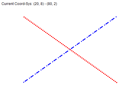
CC.Paint 1, Cairo.CreateSolidPatternLng(vbWhite) 'fill the entire Surface with White
DrawSquaredLineDots 30, 3, 70, 7, vbBlue
DrawDottedLine 70, 3, 30, 7, vbRed
CC.TextOut 5, 5, "Current Coord-Sys: (" & CoTL.x & ", " & CoTL.y & ") - (" & CoBR.x & ", " & CoBR.y & ")"
Set Canvas.Picture = CC.Surface.Picture 'finally copy the result as the new Picture into our Canvas
End Sub
Private Sub DrawSquaredLineDots(x0, y0, x1, y1, Color, Optional ByVal LW# = 3)
Set CC.Matrix = CoM 'apply the non-standard Coord-Sys Matrix
CC.DrawLine x0, y0, x1, y1 'we define only the Path on the CC here
CC.MatrixResetToIdentity 'restore the original (identity)-Matrix (which is a normal Top-Down 1:1 CoordSys)
'now that we are back in the normal CoordSys, we can ensure stroking (or filling)
CC.SetLineWidth LW
CC.SetDashes 0, LW, LW, LW * 4, LW * 2 'dash-patterns are defined in alternating Pen-Down/Pen-Up intervals
CC.Stroke False, Cairo.CreateSolidPatternLng(Color) 'close the Path (with False) after Stroking it with a Color
End Sub
Private Sub DrawDottedLine(x0, y0, x1, y1, Color, Optional ByVal LW# = 4)
Set CC.Matrix = CoM 'apply the non-standard Coord-Sys Matrix
CC.DrawLine x0, y0, x1, y1 'we define only the Path on the CC here
CC.MatrixResetToIdentity 'restore the original (identity)-Matrix (which is a normal Top-Down 1:1 CoordSys)
'now that we are back in the normal CoordSys, we can ensure stroking (or filling)
CC.SetLineWidth LW
CC.SetLineCap CAIRO_LINE_CAP_ROUND 'it's the Line-EndCaps, which ensure the Dots - therefore the Down-Pen-Phase we define below is very short
CC.SetDashes 0, 0.01, 1.5 * LW 'dash-patterns are defined in alternating Pen-Down/Pen-Up intervals
CC.Stroke False, Cairo.CreateSolidPatternLng(Color) 'close the Path (with False) after Stroking it with a Color
End Sub
Private Sub Form_Terminate()
If Forms.Count = 0 Then New_c.CleanupRichClientDll
End Sub
Here is the uploaded PNG-File, which the above code produced by clicking the Form:
Thanks so much Olaf, as always thankful for your help.
PK
If you go this way (regarding your valves or other Symbols you want to draw at certain "Center-Point-Coords", rotated or not...) -
you can either:
- construct them yourself with Cairo-Drawing-Commands as SVG-Files (for later usage from your own Symbols-Repository)
- or make use of existing ones (as e.g. the ones from this Link here: https://www.svgrepo.com/svg/2742/valve)
..(in the latter case above, just make sure to check the License, giving proper attribution when it's under CCO or something)
The approach would also allow you, to combine anything you render onto "a CC",
into either a larger Export-SVG - or into a larger Export-PDF directly.
I have a very interesting application that I work on, and your contribution will greatly advance my ideal solution.
I have a Google background on which I draw pipes and nodes. I then zoom into select places depending on the mouse_up event X and Y coordinates. Valves are shown at this stage as only legends like crosses as said above. (almost completed).
When I zoom in even more, I wish to show what is hapenining at those nodes in terms of pipe fittings like valves etc. such as sketches or real photos of valves etc..
Zooming in even more, I wish to show detail of the node like photos, drawings or photorealistic images which I develop from the drawings. In such a case I will remove the Google background and replace it with these other pictures or bitmaps.
I am quite sure it is feasible, exciting and novel.
What I miss is the properties and events of the vbRichClient. Is there a document available which explains that?
What I miss is the properties and events of the vbRichClient. Is there a document available which explains that?
There is *.chm documents on https://vbRichClient.com/Downloads/RC5Chms.zip
But even faster is <F2> or <Shift><F2>(to get help for a certain Method) -
which will land you in the VB6-ObjectExplorer-Window of your IDE.
For Drawings, you basically only need to understand the methods of the cCairoContext-Class -
(which is usually present in that "CC"-Variable I use in my Demos).
As for SVG-support (rendering your Valves and other Symbols) -
here is a little Sub which can render these in the context of the above example,
based on Center-Coords (also supporting the size of the Symbol in dx, dy + Rotation in the RotDeg-Param):
Code:
Private Sub RenderSVGCentered(ByVal cx#, ByVal cy#, dx, dy, RotDeg, SVGBytes() As Byte)
  Dim SVG As cSVG: Set SVG = New_c.SVG
      SVG.ParseContent SVGBytes

  CoM.CalculatePoint cx, cy 'use the Matrix, to transform the (ByVal) passed center-point-coords into User-Coords on the 1:1 CoordSys

  CC.Save 'prepare for Coord-Changes (protecting the "outer" CoordSys)
    CC.TranslateDrawings cx, cy
    CC.RotateDrawingsDeg RotDeg
    CC.TranslateDrawings -dx / 2, -dy / 2
    SVG.RenderFromDOM CC, 0, 0, dx, dy
  CC.Restore 'restore the outer Coord-Sys
End Sub
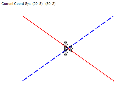
Usage then (when you place the following line in the central Refresh-Routine of the first example)...
Code:
  'the center-point (below 50,5) has to be given in your "off-standard-coords", but the Symbol-Size (below given as 48, 48) in "normal Pixels".
  RenderSVGCentered 50, 5, 48, 48, 90, New_c.FSO.ReadByteContent("c:\temp\valve-svgrepo-com.svg")
The above assumes, that you've placed the "Valve-SVG" I've posted a Download-Link for, in "c:\temp").
Then producing this output (after integration of the above line into the Refresh-Routine either above or under the two "Line-Calls"):
I am trying to implement the valve routine just as you said.
However, there are a few things I am doing wrongly ... and by this time you are so used to me doing that and asking trivial questions.
The Canvas that you refer to .. can that be my Picture1, the picturebox I am drawing on.
When I do that, it clears my own elements drawn every time I invoke RefreshCanvas.
When the CoBR.x - CoTL.x and CoBR.y - CoTL.y terms becomes zero, it gives the standard division by zero error.
Let me try and implement it step by step. As a first step I wish to convert my X1,Y1 and X2.Y2 coordinates to the converted coordinates and calculating the converted length between them. What code would do that? (I can read the code, but am uncertain about its implications)
The Canvas that you refer to .. can that be my Picture1, the picturebox I am drawing on.
Yes... the Demo is currently passing the Form-Object as a Canvas, but a VB.PicBox has compatible methods.
Originally Posted by Peekay
When I do that, it clears my own elements drawn every time I invoke RefreshCanvas.
Yep - as it is implemented currently - it is "either the one - or the other".
One can merge existing PicBox-Content with a few extra-lines
(for example, when "the Cairo-Ops shall come last", then it would be quite easy -
to "clear" the cairo-canvas not with "plain, solid white Color", but with the existing PicBox-Content).
Originally Posted by Peekay
When the CoBR.x - CoTL.x and CoBR.y - CoTL.y terms becomes zero, it gives the standard division by zero error.
Sure... I left this sanity-check out - because using the whole approach only makes sense, when you have a Coord-Sys with some "extents".
Originally Posted by Peekay
Let me try and implement it step by step. As a first step I wish to convert my X1,Y1 and X2.Y2 coordinates to the converted coordinates and calculating the converted length between them. What code would do that? (I can read the code, but am uncertain about its implications)
I've placed an appropriate Line in the little SVG-Render-Routine in my last post:
Code:
CoM.CalculatePoint cx, cy 'use the Matrix, to transform the (ByVal) passed center-point-coords into User-Coords on the 1:1 CoordSys
Here is a separate routine you can play around with, which should clarify the behaviour of the Matrix:
Code:
Private Sub MatrixConversionsTest(ByVal px#, ByVal py#)
  CoM.CalculatePoint px, py 'use the Matrix, to transform the (ByVal) passed point-coords into User-Coords on the 1:1 CoordSys

  Dim DistPxl#: DistPxl = Sqr(px * px + py * py) '<- calculate the Pixel-Distance (after px/py were converted "on the spot" above)

  Dim DistX#, DistY#: DistX = DistPxl: DistY = DistPxl '<- copy this value over into DistX/Y
  CoM.Invert.CalculateDistance DistX, DistY 'and pass these into a Distance-Calculation on the inverted Matrix

  Debug.Print "Distance in Canvas-Pixels: " & DistPxl
  Debug.Print "Distance, when walking 'straight on the X-Axis': " & DistX
  Debug.Print "Distance, when walking 'straight on the Y-Axis': " & DistY
End Sub
I checked the metods and properties of this Matrix class, but need some elucidation.
I need some help on the following please:
I am trying to do this routine:
Code:
Private Sub DrawValveOlaf(Canvas As Object, XTL As Single, YTL As Single, XBR As Single, YBR As Single, X1 As Single, Y1 As Single, X2 As Single, Y2 As Single, ValveType As String, Optional ValveOpen As Boolean, Optional ValveDirection As Integer)
Dim transX1 As Long, transY1 As Long, TransX2 As Long, TransY2 As Long, LineLengthInPixels as long

With Canvas
    .ScaleMode = vbPixels
    Set CC = Cairo.CreateSurface(.ScaleWidth, .ScaleHeight).CreateContext
End With

CoTL.x = XTL: CoBR.x = XBR
CoTL.y = YTL: CoBR.y = YBR

Set CoM = Cairo.CreateIdentityMatrix
    CoM.ScaleCoords CC.Surface.Width / (CoBR.x - CoTL.x), CC.Surface.Height / (CoBR.y - CoTL.y)
    CoM.TranslateCoords -CoTL.x, -CoTL.y

    transX1=???
    transY1=???
    transX2=???
    transY2=???

    LineLengthInPixels=sqr((transX2-transX1)^2+(transY2-transY1)^1)

    Canvas.Line(transX1,transY1)-(transX2,transY2),vbRed

End Sub
To do this properly, you'd have to forego any attempts of rendering via PicBox-Drawing-Methods or GDI-Drawing-Methods.
If you want to accomplish "a mix", then the result will be utter chaos (and our threads will get super-long, which I currently have no time for).
Perhaps we should establish a bit of "common ground" first...
When you say: I have a Google background on which I draw pipes and nodes...
How do you get this "Google-BackGround"?
Is it always "a single Tile" (retrieved from Google-WebAPI)?
Or is it a "combination of several Tiles, rendered with different Offsets in a VB.PictureBox"?
Assuming "Singe-Tile" - do you have that tiles TopLeft and BottomRight-Coords (in Lat/Lon-Format),
or do you only have the "center-coord of a given Tile"?
What Size are the Tiles in Pixels when you get them from a WebAPI (512x512, 640x640)?
Can you upload such a Tile-PNG or Tile-JPG (along with its Lat/Lon-Corners or Center-Point)?
I ask all this, because that's the first thing you will have to accomplish (properly managing the Tile-based BackGround).
The Coord-System Matrices will play into that - they certainly don't belong into each and every little renderin-routine.
(they will only have to be updated, when your Tile, or Tile-Position changes, or when your PixBox-Container changes size).
What I do is that I have about 50 Google Earth pictures each covering 1 degree of latitude and 1 degree of longitude. These I load each into its own picturebox with LoadPicture, everytime the location or scale changes, I only load those I need for the new view for that specific location and scale. They are each scaled to their lat and long sizes, such as in pic.scale(thislat,thislong)-(thislat+1,thislong+1). Call them picDetail(0) to whatever I need - normally about 9 of these.
I then populate the Picture1 picturebox, which may cover any area depending on its location and scale. So I set its scale like in Picture1.scale(LatStart,LongStart)-(Laststart+latwidth,LongStart+longwidth)
I then use Picture1.Paintpicture to place these needed picDetails() into the Picture1 picturebox. This I have done very successfully.
I then draw my pipes and nodes on this Picture1 picturebox and the pipes and nodes fit quite nicely on the Google background, as I have done my scaling for all these picture boxes on one consistent geo system.
Then I need to draw valves on the pipes. These valves are just two circle pies with their centres coinciding but pointing in opposite directions - see figure attached, but I cannot do that correctly because verical pointing valves will have different scales than horizontal pointing valves, due to the difference in scale ratios.
What I do is that I have about 50 Google Earth pictures each covering 1 degree of latitude and 1 degree of longitude.
I take it, that:
- each of these ~50 Tile-Images exist as a JPG in a Folder (probably named Tile_00_00.jpg up to Tile_07_07.jpg or something).
- and that each of the Tiles has the same Pixel-Size
What is the exact Pixel-Size of one of those Tile-JPGs?
And since I assume, that your Pipeline-Graphs are given in absolute Lat/Lon Polygon-Coords,
you have to have an absolute Lat/Lon Reference-Point for the TopLeftCorner of the most Top-Left Tile (the one in your File-System, named Tile_00_00.jpg).
I'm willing to provide you with a small example, how to manage these Tiles via Cairo
(probably around 30 lines of code, without using any PicBoxes), but I need:
- your TileImage-Foldername (relative to the App.Path)
- your current naming Scheme of the Tile-Images in your Tile-Folder (to be able to find the right Image, according to the relative Lat/Lon-Offsets)
- the Tile-Image-Pixelsize
- and the absolute Lat/Lon of the TopLeftCorner of the most TopLeft Image-Name
Then I could "mock something up, pretty fast" (using self-generated Mock-JPGs as Tiles - which will match your naming-scheme)
Olaf,
I know what you want and will next time give it all, but before I involve you in a long story, which you always do for me regardless of what it takes.
Firstly, what is quite easy in my tile setup scheme, is that I use the left top left coordinates to name my Detail files, like in 'Google 26-25.jpg' means it starts at the 26 deg latutude and 25 deg. longitude.
What I first wish to pursue is something which I think may provide a trivial solution.
I know what angle a pipe makes in the standard cartesian, so I can calculate how many pixels a 1 metre long pipe takes at that specific angle. Then I calculate the begin and end coordinates of the valve in pixels, at my required pixel length, and then convert it back to .scalecoordinates.
That sounds trivial and might work.
On reflection, the mathematical solution to this problem is probably the easiest. The size of a constant diameter pixel circle can be transformed into a ellipse of .scalecoordinates. So, I only need to find the general solution for the ellipse to handle all angles.
PK
Last edited by Peekay; Feb 12th, 2021 at 01:57 PM.
What I first wish to pursue is something which I think may provide a trivial solution.
I know what angle a pipe makes in the standard cartesian, so I can calculate how many pixels a 1 metre long pipe takes at that specific angle. Then I calculate the begin and end coordinates of the valve in pixels, at my required pixel length, and then convert it back to .scalecoordinates.
That sounds trivial and might work.
But I'm still sure, that your whole approach could profit enormously from Vector-based drawing.
Not sure, what your current amount of sourcecode is, using the "classic approach".
But the below 75 lines contain basically all the moving parts one might need for stuff like this:
- including how to do a dynamic Map-Image-Resource Download (under a given ImageKey)
- a single VB.PictureBox (to finally show the CC-constructed Vector-Output)
- applying proper Map-Offsets to dynamically place such an Image as the BackGround
- it shows, how to draw a simple Line
- then applies 3 "special, angled renderings" on that line (two "circled Text"-outputs + "a Valve")
- clicking the Command1-Button applies a goblal Zoom to the renderings (including the Map-Background)
- the ZoomFactor does not have to be included in any "special math" within the rendering-subroutines (these do not know, that they "were zoomed")
Here is, how it currently looks with ZoomFactor = 1.0:
And here, how it looks after pressing Command1 a few times:
Note, how *all* the Vector-Drawings on top of the map are scaled properly (including the Line-Width)
Ok, here's the code (the Form needs a Picture1 and a Command1 placed on it).
Code:
Option Explicit

Private CC As cCairoContext, ZoomFac As Single

Private Sub Form_Load()
  DownloadMapResource New_c.Downloads, "sa_map", "http://vbRichClient.com/Downloads/sa_map.jpg"
  ZoomFac = 1 'start the App with a ZoomFactor
  Caption = "Current ZoomFactor = " & ZoomFac
End Sub

Sub DownloadMapResource(DLs As cDownloads, ImgKey As String, URL As String)
  With DLs.Download(URL)
       .WaitForCompletion
    If .GetContentLen Then Cairo.ImageList.AddImage ImgKey, .GetContentData
  End With
End Sub

Private Sub Form_Resize()
  On Error Resume Next
  Picture1.Move 0, Picture1.Top, ScaleWidth, ScaleHeight - Picture1.Top
End Sub

Private Sub Command1_Click()
  ZoomFac = ZoomFac + 0.2
  Caption = "Current ZoomFactor = " & ZoomFac
  RefreshCanvas
End Sub

Private Sub Picture1_Resize()
  Picture1.ScaleMode = vbPixels 'synchronize the Backbuf-CC to the exact PixelSize of the Picture1-Canvas
  Set CC = Cairo.CreateSurface(Picture1.ScaleWidth, Picture1.ScaleHeight).CreateContext
  RefreshCanvas
End Sub

Sub RefreshCanvas()
  CC.Save
    CC.ScaleDrawings ZoomFac, ZoomFac 'apply a global ZoomFactor for all the follow-up-renderings

    RenderMapBackGround 200, 830

    Dim x0, y0: x0 = 100: y0 = 222 'define the Lines start-
    Dim x1, y1: x1 = 333: y1 = 100 '...and end-Point

    CC.DrawLine x0, y0, x1, y1 'define the "from-to" line-path
    CC.Stroke False, Cairo.CreateSolidPatternLng(vbRed) 'stroke this line-path

    Dim ll: ll = Sqr((x1 - x0) ^ 2 + (y1 - y0) ^ 2) 'calc the Line-Length
    Dim ar: ar = Cairo.CalcArc(y1 - y0, x1 - x0)    'and Line-Angle in Radians

    DrawCircledTextFrom x0, y0, 0.2, ll, ar, 13, "001"
    DrawValveFrom x0, y0, 0.5, ll, ar, 18
    DrawCircledTextFrom x0, y0, 0.8, ll, ar, 13, "002"
  CC.Restore

  'the refresh-cycle on our CC is done, so we put the results as a Picture into the VB.PictureBox
  Set Picture1.Picture = CC.Surface.Picture
End Sub

Sub RenderMapBackGround(MapOffsX, MapOffsY)
  CC.RenderSurfaceContent "sa_map", -MapOffsX, -MapOffsY
End Sub

Sub DrawCircledTextFrom(x0, y0, llPerc, ll, ar, Radius, Text As String)
  CC.Save
    CC.TranslateDrawings x0, y0  'apply x0, y0
    CC.RotateDrawings ar 'now (after shifting) we can also apply the line-angle as well
    CC.TranslateDrawings llPerc * ll, 0 'which makes the final shift trivial to apply

    CC.Arc 0, 0, Radius 'draw a filled circle
    CC.Fill False, Cairo.CreateSolidPatternLng(vbWhite, 0.75)

    CC.SelectFont "Arial Narrow", 10 'start Text-Output, beginning with Font-Selection
    Dim TW#, FH#: TW = CC.GetTextExtents(Text, FH) 'calc TextWidth and FontHeight for the current Font and Text
    CC.TextOut -TW / 2, -FH / 2, Text, , , True 'build the Text-Path (with offsets for centered output)
    CC.Fill False, Cairo.CreateSolidPatternLng(vbBlack) 'fill the Text-Path

  CC.Restore
End Sub

Sub DrawValveFrom(x0, y0, llPerc, ll, ar, Radius)
  CC.Save
    CC.TranslateDrawings x0, y0  'apply x0, y0
    CC.RotateDrawings ar 'now (after shifting) we can also apply the line-angle as well
    CC.TranslateDrawings llPerc * ll, 0 'which makes the final shift trivial to apply

    CC.MoveTo 0, 0 '3 lines to construct "a pie" (with now relative coords, based on our new 0,0-CoordSys)
    CC.Arc 0, 0, Radius, -0.6, 0.6 'the last two params define the start-angle and end-angle of the pie in radians
    CC.ClosePath

    Dim tmpP As cCairoPath 'define a temp-variable for the above Path
    Set tmpP = CC.CopyPath 'and copy the currently constructed Path into it

    CC.AppendPath tmpP 'apply the temp-path and stroke it
    CC.Stroke False, Cairo.CreateSolidPatternLng(vbGreen)

    CC.RotateDrawingsDeg 180 'since the two parts of a valve are symmetric, we just have to rotate 180 deg

    CC.AppendPath tmpP 'and can now apply the temp-path again for that second part of the valve
    CC.Stroke False, Cairo.CreateSolidPatternLng(vbYellow)

    CC.Arc 0, 0, Radius * 0.3 ' finally we render a completely filled arc into the valves center-point
    CC.Fill False, Cairo.CreateSolidPatternLng(vbWhite, 0.75) '<- using 75% Alpha

  CC.Restore
End Sub
Maybe this little "wire-frame"-example helps others who have similar "mapping-scenarios" -
(I've commented "decent engouh", I think).
Can you please elaborate on this file saving code:
Code:
Private Sub Form_Click() 'besides reflecting into a Picture-Object, one can always render a Png or a Jpg from a CC.Surface
  CC.Surface.WriteContentToPngFile "c:\temp\canvas_output.png"
End Sub
Should I first set CC I presume.
Code:
Dim CC As cCairoContext
Set CC = Cairo.CreateSurface(picCompiled.ScaleWidth, picCompiled.ScaleHeight).CreateContext
CC.Surface.WriteContentToJpgFile "C:\OneDrive\My Programs\Google Maps\picCompiled.jpg"
It only makes a file of 1KB.
I need to save a picturebox which I compilated from many tiles as a .jpg file.
Here is how I compiled that picturebox and I can see it was compiled correctly.
Code:
On Error GoTo NoPicture
Dim PictureAndPathname As String, PictureName As String
pb.Value = 0
fraProgress.Visible = True
For i = 17 To 25
    pb.Value = (i - 17) * 12
    For j = 31 To 25 Step -1
        PictureAndPathname = App.Path & "\Google Maps\Google " & CStr(i) & "-" & CStr(j) & ".jpg"
        PictureName = "Google " & CStr(i) & "-" & CStr(j) & ".jpg"
        picTemp.Picture = LoadPicture(PictureAndPathname)
        picCompiled.PaintPicture picTemp, i, j, 1.001, -1.001
10    Next j
Next i
fraProgress.Visible = False
On Error GoTo 0
Thanks
PK
Last edited by Peekay; Feb 15th, 2021 at 12:40 AM.
I need to save a picturebox which I compilated from many tiles as a .jpg file.
Here is some AirCode
(untested, you might want to fiddle around with your indexes and offsets, to produce the right result -
but maybe it already works on the first try...).
Code:
Private Sub StitchJpgs()
  Dim i&, j&, Tmp As cCairoSurface, CC As cCairoContext

  For i = 0 To 8
    For j = 0 To 6
      Set Tmp = Cairo.ImageList.AddImage("", App.Path & "\Google Maps\Google " & (i + 17) & "-" & (j + 25) & ".jpg")
      If CC Is Nothing Then Set CC = Cairo.CreateSurface(Tmp.Width * 9, Tmp.Height * 7).CreateContext

      CC.RenderSurfaceContent Tmp, i * Tmp.Width, j * Tmp.Height, Tmp.Width * 1.001, Tmp.Height * 1.001
    Next
  Next

  CC.Surface.WriteContentToJpgFile App.Path & "\Google Maps\Stitched.jpg"
End Sub
Olaf,
Why does it generate an Out of memory error after Then in this line: (that is for i=1 and j=1 both declared as long.)
I have a reference to vbRichClient5 selected
Code:
Dim PictureAndPathname As String, PictureName As String, Tmp As cCairoSurface, CC As cCairoContext

If CC Is Nothing Then Set CC = Cairo.CreateSurface(Tmp.Width * 9, Tmp.Height * 7).CreateContext
PK
Last edited by Peekay; Feb 15th, 2021 at 09:34 AM.
Olaf,
Why does it generate an Out of memory error after Then in this line: (that is for i=1 and j=1 both declared as long.)
I have a reference to vbRichClient5 selected
Code:
Dim PictureAndPathname As String, PictureName As String, Tmp As cCairoSurface, CC As cCairoContext

If CC Is Nothing Then Set CC = Cairo.CreateSurface(Tmp.Width * 9, Tmp.Height * 7).CreateContext
As the error-description told you, the VB6-IDE-Process-instance which executed that code, ran out of memory.
One of the reasons might be, that the IDE-Process was already "under memory-stress"...
E.g. when you placed the source-snippet not in an "empty, virginal IDE-Project" but in the context of your "real Project" -
(which might have about 60 Tiles already defined, or loaded on a Form in your PicBox-Tile-Arrays which hold BMP-resources).
But sure, Cairo.CreateSurface(Wpixels, Hpixels) will attempt a single contiguos mem-allocation
(with 32Bit per Pixel, meaning a 4 Byte-Multiplicator)
e.g. a 1024x1024 cairo-surface will take up: 1MegaPixels * 4 Bytes = 4MB
I'm not sure, whether I'm right with my assumption (you never tell these things beforehand) -
that you have:
- 9 tiles horizontally (in "x-direction")
- and 7 tiles vertically
I also don't know
- the concrete pixel-dimensions of a single tile
- and also not, whether these pixel-dimensions are the same "across all of your tiles"
What I assumed was some 640x640 Tile or max 800x800 tiles.
which is: 4&*800*800 = about 2.5MB fo a single tile
Multiplied by 63 gives about 160MB total for the stitched-surface,
which the memory-manager has to find in a consecutive allocation-block.
A lot of assumptions on my part (which you hopefully clear up) -
but if your Tiles are more in the range of 1024x1024, then a single consecutive allocation for the "stitched surface" -
would need about 4MB * 63 ~250MB already ... and so on.
One could stretch down any incoming single tile about a certain percentage in that loop,
so that the "stitched sum of the single tile-parts" results in a lower "over-all-size" of the combining surface.
But one would need at least the aspect-ratio of a single tile for that - which I also do not have.
I understand that much better now.
The tiles are about 800 kB each, but Creating the surface needs a canvas of 13698x9919, which is the problem.
I shall have to revert to my original routine where I only loaded the tiles which I needed for that zoomfactor.
For the large compiled canvas I can use a picture which is of low resolution and step up the resolution as I zoom in.
I must say your vbRichClient classes and handling of pictures are quite incredible.
I could provide you with a more flexible stitching-routine (which does reduce the size of the final surface a bit) -
but as said would at least need the following questions answered:
- the concrete pixel-dimensions of a single tile-JPG
- and also whether these pixel-dimensions are the same "across all of your tiles"
The tiles are all an average of 1520 pixels x 1420pixels plus or minus a deviation of about 5% being 1 degree in latitude and longitude.
The variation is just because it is not possible to zoom precisely with Google Earth, or at least I have found it to be so.
My predicament is that as I zoom into the map, I need to show finer detail, with the result that the 1 degree tiles are also no good for scalewidths of 0.1 degree, unless I make 3200 tiles ... so I have to stop somewhere, which would probably be at half a degree scalewidths and 120 tiles.
The final solution would be to have Google Earth as a live background, which I can zoom as I like, with a transparent canvas on top of it on which I can draw what I like, but that is wishful thinking.
The tiles are all an average of 1520 pixels x 1420pixels plus or minus a deviation of about 5% being 1 degree in latitude and longitude.
That's already sufficient info, to build a more decent stitching-routine
(which now allows you to adjust the resulting size via internal Const-Parameters):
Code:
Private Sub StitchJpgs()
  Dim CC As cCairoContext, TFile$, i&, j&

  Const TW As Long = 856, TH As Long = 800 'reduced tile-width/height according to the aspect-ratio of 1520x1420
  Const TCX As Long = 9, TCY As Long = 7   'tiles-count in x- and y-direction

  'ensure the larger stitched-surface (based on the Const-info above) - and derive a Context from it
  Set CC = Cairo.CreateSurface(TW * TCX, TH * TCY).CreateContext

  Dim MapPath As String: MapPath = App.Path & "\Google Maps\" 'the path, where the Tile-Jpgs reside
  Const ToffsLon = 17, ToffsLat = 25 'Longitude and Latitude-Offsets of the most TopLeft tile

  For i = 0 To TCX - 1: For j = 0 To TCY - 1
      'build the filename of the current tile-image (with a longitude, latitude-offset)
      TFile = MapPath & "Google " & (i + TOffsLon) & "-" & (j + ToffsLat) & ".jpg"

      'load- and render the current tile-surface onto the larger stitched surface
      CC.RenderSurfaceContent Cairo.ImageList.AddImage("", TFile), i * TW, j * TH, TW, TH
  Next j, i

  CC.Surface.WriteContentToJpgFile MapPath & "Stitched.jpg" 'place the new stitched JPG in the MapPath
End Sub
With that somewhat reduced tile-size of currently 856x800 (according to your tile-aspect-ratio) -
the routine will now dynamically stretch down to, you will get a resulting stitched-image size of about:
856*9 x 800*7 = 7704x5600 = about 170MB surface-memory
(which is still in a size, that normally will not cause any probs with memory-allocation).
Olaf,
One last thing please.
How do I move the 'stitches.jpg' image around on my Picture1 control.
What I actually want to know is whether to keep the picurebox in pixels and convert from scale to pixels to draw my scaled elements or the other way round.
I presume that ends our excursion into dashed lines, but the incredible thing about you is that I learn a new technology whenever you comment here.
Thanks, I really appreciate.
PK
Last edited by Peekay; Feb 17th, 2021 at 11:20 AM.
Under RenderSurfaceContent DstX,DstY,DstDX,DstDY, I cannot get those four values to follow my command, if you can please elaborate on that.
My picture from which I render, named picOneDegree, which contains the file 'Stitched.jpg', is in pixels, and my picture into which I render, Picture1, is in degees.
...my picture into which I render, Picture1, is in degees.
That was helpful (as a side-information).
But before I come up with something - could you give the other missing info,
whether all the Coords of "the stuff you'll draw on top", meaning:
- your Lines (or your Polygons)
- and your "Points of interests" (no matter, if "circles", "squares" or "valves")
are all in "degree-coords" as well? (degree-coords meaning: Longitude-Coords in "x", and positive (South-)Coords for the Latitude in "y"-direction)
Olaf,
I have only one picturebox named Picture1 into which I render everything in lat and long degrees and all my points, symbols or lines of interest are placed according to geo location, although, as you have seen, I draw pipelines with labels, nodes and valves with labels and flowdata in and out of pipes and nodes in labels in cjrcles or boxes at any location I want to.
I then pick up any point on the picture with the mouse move event which gives me geolocation anywhere on the picture.
I stitch Google photos together in picGoogle or any other invisible picturebox from where I render into Picture1.
I can allocate degrees lat and long already when I load from the file into any hidden picturebox, or I can keep them in vbPixels, depending on the ease with which it can be done.
In this manner I can have stitched pictures for grids of 4 degrees x 4 degrees, 2 x2 1x1, 0.5 x 0.5 degrees to my heart's delight.
The problem is knowing which part of each stitched picture to display on Picture1 and where in the box to display it.
For instance, a user may click on any place in the Picture1 box, then I must place that point in the centre of Picture1 and blow up the detail around it.
I kerp x as latitude horizontal and Y as longitude vertical. Left top will be 25S,30E and rightbottom 32S,24E. This depends on whether the project has larger x than y, or vice versa, to enable landscape viewing.
Thanks
PK
Last edited by Peekay; Feb 19th, 2021 at 10:31 AM.
I have used the routine by Schmidt in #34 above, which works very well, except that it makes white lines about one to two pixels wide between the stitched pictures, and I have been unable to remove these lines when stitching.
My tiles are all exactly the same size, so this should not happen, but what I find is that the lines are mostly horizontal and not vertical.
The horizontal stitching works well, but it might that the vertical lines may appear in certain circumstances which I have not experienced yet, for the same reason that it appears horizontal.


 Reply With Quote