I need to put together an algorithm that plots a random 3D path that looks something like what a fish's path would be in a fish tank.
I suppose another way to think of it is a screen-saver-type balls that moves around on the screen but always curves before hitting the sides. It would also get larger-and-smaller to simulate the third-axis.
In all cases, its range would be a bounded cube of arbitrary dimensions. I'd also like to control speed, but it could be relatively constant for any particular run. I'll think more about velocity once I get something up and running.
It'd just be a perpetual path.
Initially, I've thought of looking at some of the functions for French curves, or possibly adapting a Bézier curve, but I'm open to ideas.
I don't have any need to follow any particular function or algorithm, so long as it's a nice looking function. However, it will need to have a random component to it.
I'll keep exploring options, but suggestions are welcome.
Initially, I'll probably mock it up as a dot in a scaled picturebox.
Best Regards,
Elroy
p.s. I know this may more belong in a math forum than here. But I know y'all better than I know any of those guys. And I also suspect some great ideas will be provided here. Also, they'll also be more in code form rather than pure math algorithms.
Last edited by Elroy; Jan 27th, 2019 at 02:08 PM.
Any software I post in these forums written by me is provided "AS IS" without warranty of any kind, expressed or implied, and permission is hereby granted, free of charge and without restriction, to any person obtaining a copy. To all, peace and happiness.
Hmmm, so you are looking at some sort of path generator with relatively smooth directional changes. I'd assume the target can change directions at all 6 sides of the cube? And the new direction can be any of the 6 (except the current direction obviously)?
There is a project I wrote when I was on PSC, named "WordArt", linked here. I'm not suggesting that at all. However, in that project is a test where a wild path is created and the code moves a ball/circle along the path, precisely. If you take a look and the path tracing example and if it is something like you are looking for, I could probably offer some tips/ideas. Note that the code relies on beziers vs French or otherwise. That project is also GDI+ based, just FYI
Edited: The path tracing logic is based off this function and source is credited in that project. Variables a,b,c,d are the 4 points related to a bezier. In that project of mine, clsWApath.NavigatePath is where all the magic happens. FYI: flat lines are dynamically coerced into "flat-beziers" to enable them to be navigated as a bezier.
Code:
float bezierInterpolation(float t, float a, float b, float c, float d)
{
float
tSquared, tCubed;
tSquared = t * t;
tCubed = tSquared * t;
return (a
+ (-a * 3 + t * (3 * a - a * t))) * t
+ (3 * b + t * (-6 * b + b * 3 * t)) * t
+ (c * 3 - c * 3 * t) * tSquared
+ d * tCubed;
}

"t" should be a value between zero and one.
Last edited by LaVolpe; Jan 27th, 2019 at 03:16 PM.
Insomnia is just a byproduct of, "It can't be done"
@LaVolpe: Yeah, I grabbed the project in your link. I figured a Bézier was going to be the way to go. In fact, I wasn't really worried about producing a Bézier curve. I'm still very much in the conceptual stage of this thing, but I'm thinking that detecting the boundaries (adjusting the curve appropriately), and also incorporating a perpetual random component are going to be the difficult aspects of this thing.
Also, I suspect I'll "pick" on this thing over the next few days. It's not something I'm trying to knock out quickly.
Just to put a touch of meat on the bones, I'm imagining some of the input parameters to be something like:
Code:
Type PathRange
    MinX As Double
    MaxX As Double
    MinY As Double
    MaxY As Double
    MinZ As Double
    MaxZ As Double
End Type
I'm thinking it'll also have some initialize parameter that specifies the desired approximate Euclidean distance between the points. And then, some function you just repeatedly call that returns points on the curve.
Undoubtedly, this function will have several statics to remember where it was the last time it was called.
And, setup like that, I can deal with velocity entirely outside of the function.
I'll definitely be studying Bézier curves to see how I can establish bounds for them, and also incorporate a random component.
Thanks for your Thoughts,
Elroy
Any software I post in these forums written by me is provided "AS IS" without warranty of any kind, expressed or implied, and permission is hereby granted, free of charge and without restriction, to any person obtaining a copy. To all, peace and happiness.
I'll use GDI+ path structure since I know it well. GDI path structure is probably similar.
You may want to include sub-paths. In GDI+ a sub-path is a portion of the entire path, technically called a path marker. Let's say you have a path like an oval that consists of 4 parts: 2 lines and 2 semicircles. The 2 lines are horizontal to the viewer and the semicircles are moving away from or towards the viewer depending on direction of travel. If you use the sub-path idea, you can attach directional properties to them and can attach other attributes, like a velocity offset. For example, let's say that if the ball is moving towards the viewer, it travels slightly faster than horizontally and if moving away from the viewer, it travels slightly slower. We can also add depth attributes to them so that parts of the oval are considered further away from the viewer than the other half.
With each sub-path (path marker), there would be enough attribute information to adjust speed relative to direction from viewer and size of ball relative to distance from viewer
As far as a path algorithm, lots of discussion can happen there. Since you want perpetual paths, obviously the starting/ending point are likely be the same point. One idea would be to start at one end of the cube and always move towards the opposite end. During that travel, the path can randomly move away/towards the viewer while still angling toward the end of the cube. As the path touches a boundary, it alters direction but still towards end of cube. Once the path hits the end of the cube, the path can be mirrored to return to its original starting point. Or a similar algorithm can be run in reverse to finish off the path.
In any case, once the path has been plotted, a ball can be placed at any point on the path and then be animated along the path perpetually.
Above is just thinking out loud & didn't even address collisions when multiple balls are in motion along crisscrossing paths.
Last edited by LaVolpe; Jan 27th, 2019 at 07:28 PM.
Insomnia is just a byproduct of, "It can't be done"
LaVolpe, I can see I got your gears turning a bit.
At present, I've got no need to worry about collisions of multiple balls. In other words, my fish can swim right through each other (even if I were to ever have more than one fish).
In terms of an end-point, I don't think I want one. Sure, there's got to be a starting-point, but that's just any arbitrary point within the cube. And I'd be fine if it's just the cube's centroid.
Also, I'd prefer to not collide with the walls of the cube. We might make curving tangents with it. Or, if it's a shallow collision, possibly just mirror (or flip) the angle to put a small kink in the curve. But I'd like to avoid near-head-on collisions.
And, the more this thing simmers in my head, I've come up with some conclusions:
1) I think I should try to get a 2D version going, and then expand that to 3D once I'm happy at 2D.
2) I think I should just focus on the center of the balls as what doesn't collide with a wall. Adjusting for ball-size can be done later.
3) I think I should get notions of Bézier or French curves out of my head. I think that's where I'm getting hung up. I'm starting to think the curve should be defined by the prior direction vector and the current proximity to walls, making angle adjustments to the next direction vector, and becoming more dramatic the closer we are to a wall (possibly with a touch of randomness thrown in there). Approaching a corner may be a bit tricky, but I'm thinking something will become obvious once I get some code up and running.
And, on that note, I eventually will start writing some code, once I figure out some plan-of-attack for this thing. Regarding GDI or GDI+, I'll probably just start with a simple PictureBox and its intrinsic plotting abilities. Once I get some math algorithm going, I may then embrace some of that stuff.
And I'm really thinking this thing is going to have a heuristic solution, rather than some pure math solution. In that sense, I think I truly am in the correct forum.
Thank You,
Elroy
EDIT: And if I actually do get a full 3D algorithm up and running, I'll possibly lean on DirectX to plot it. It'd be pretty cool to be able to grab the cube and rotate it around, watching the ball curve around inside of it.
Last edited by Elroy; Jan 28th, 2019 at 11:12 AM.
Any software I post in these forums written by me is provided "AS IS" without warranty of any kind, expressed or implied, and permission is hereby granted, free of charge and without restriction, to any person obtaining a copy. To all, peace and happiness.
Elroy, don't get too wrapped up in beziers, per se. You can use an API to draw them between 2 points for testing as the paths won't be visible otherwise. The nr of pixels the bezier would arc away from the near/far points are controlled by you. Think of a bell curve. You can make the peak of the curve higher or lower. So, I wouldn't focus too much on colliding with cube walls. Simply reduce the cube dimensions, within your path generator, to allow a curved direction adjustment. For example, if you are planning to use a bezier to change directions on wall collision, then you'll know how many "pixels" that bezier will extend. Reduce the cube dimensions to account for that constant. And another option is to simply ignore that scenario, allow the bezier and when the path is completely generated, "stretch" the path smaller to fit the cube. Reason I kept referencing GDI+ is that it has all the tools built in to do much of this if using paths.
However, it appears you want to pursue 3D coordinates and drawing basically a wire-diagram that resembles a path. Good idea also I think.
In either case, what you may want to get wrapped up in is how you plan on navigating the path. Lines are easy. Beziers are harder. Since your paths won't be visible, pixel perfect positioning is probably not going to be a concern, so shortcuts may be possible. But the formula I mentioned in my 1st reply and an implementation of that formula in the project I linked to may be helpful. In addition, you'll want to think about how you are going to refresh the screen for changes, i.e., order of rendering balls from furthest away to closest. Rendering entire screen/cube on small timer intervals will likely be poor performance + high CPU usage.
Edited: In that project I linked to, there is a function that creates beziers manually: clsWApath.Append_Wave
As before, above is just thinking out loud
Last edited by LaVolpe; Jan 28th, 2019 at 12:34 PM.
Insomnia is just a byproduct of, "It can't be done"
I wrote a short little experiment many years ago, but I don't have access to my computers at the moment.
Basically, you don't need curve calculations, per se.
I just pick an initial random heading, and then each frame, add a random amount, + or - to that heading. You then move based on the heading and velocity. If you add a fixed amount each frame to one side of the heading, you get a circular curve. If you add an increasing amount each frame you get a tightening spiral, and if you add a decreasing amount each frame you get a widening spiral.
I just created a number of objects and let each add a small random amount +/- each frame to the heading and watch how they moved around the space. I kept a user set variable number of object, and number of points to track for each object. I drew line segments between the tracked points. What I ended up with I called worms, because that is what it looked like. A bunch of worms that wriggled across the screen in various directions, and sometimes they would turn more this way than that, and sometimes wriggle around and reverse direction, but because they could never change heading by more than a small amount each frame, you didn't have sharp unrealistic angles in their movement.
@DllHell: That first link looks VERY promising. Regarding the second link, I'm not sure I'm up for learning all the possible theories for doing what I want, but I do appreciate the resource.
The last link also looks promising. I like the idea of using some quaternions to get this done, as they do an excellent job of tracking 3D rotation and direction (if we're always facing forward). But sadly, they didn't provide an illustrative video, so I'm not totally clear on what that code is doing. The third link seemed to be on a slightly different track.
So, it looks like I may be in for some Unity translation. Argh, I've never even looked at Unity before.
EDIT: Ok, maybe not so bad. I think the core functions are in C#, which I can deal with.
Last edited by Elroy; Jan 28th, 2019 at 12:51 PM.
Any software I post in these forums written by me is provided "AS IS" without warranty of any kind, expressed or implied, and permission is hereby granted, free of charge and without restriction, to any person obtaining a copy. To all, peace and happiness.
using System.Collections;
using System.Collections.Generic;
using UnityEngine;
using UnityEngine.Assertions;
/// <summary>
/// Provides fish behavior including swimming animation, obstacle avoidance, and
/// wandering behavior.
/// </summary>
public class Fish : MonoBehaviour
{
/// <summary>
/// A location inside the tank that will be used as a reference point when
/// calculating turns to avoid obstacles.
/// </summary>
public Transform tankCenterGoal;
/// <summary>
/// Indicates how close an obstacle must be (in meters) before the fish
/// begins to take evasive action.
/// </summary>
public float obstacleSensingDistance = 0.8f;
/// <summary>
/// The minimum speed this fish should move in meters/second.
/// </summary>
public float swimSpeedMin = 0.2f;
/// <summary>
/// The maximum speed this fish should move in meters/second.
/// </summary>
public float swimSpeedMax = 0.6f;
/// <summary>
/// Controls how quickly the fish can turn.
/// </summary>
public float maxTurnRateY = 5f;
/// <summary>
/// When the fish randomly changes direction while wondering, this value
/// controls the maximum allowed change in direction.
/// </summary>
public float maxWanderAngle = 45f;
/// <summary>
/// Sets the duration of each wander period (in seconds). At the start of
/// each wander period the fish is given an opportunity to change direction.
/// The likelihood of changing direction at each period is controlled by
/// <tt>wanderProbability</tt>.
/// </summary>
public float wanderPeriodDuration = 0.8f;
/// <summary>
/// Indicates how likely the fish is to turn while wondering. A value from
/// 0 through 1.
/// </summary>
public float wanderProbability = 0.15f;
// The current speed of the fish in meters/second.
[HideInInspector]
public float swimSpeed;
// The fish's current direction of movement.
private Vector3 swimDirection
{
get { return transform.TransformDirection(Vector3.forward); }
}
// Flag to track whether an obstacle has been detected.
private bool obstacleDetected = false;
// The timestamp indicating when the current wander period started.
private float wanderPeriodStartTime;
// The orientation goal that the fish is rotating toward over time.
private Quaternion goalLookRotation;
// Cached reference to the fish body's transform.
private Transform bodyTransform;
// A random value set dynamically so that each fish's behavior is slightly
// different.
private float randomOffset;
// Location variables used to draw debug aids.
private Vector3 hitPoint;
private Vector3 goalPoint;
/* ----- MonoBehaviour Methods ----- */
void Start()
{
// Warn the developer loudly if they haven't set tankCenterGoal.
if (tankCenterGoal == null)
{
Debug.LogError("[" + name + "] The tankCenterGoal parameter is required but is null.");
UnityEditor.EditorApplication.isPlaying = false;
}
bodyTransform = transform.Find("Body");
randomOffset = Random.value;
}
private void Update()
{
Wiggle();
Wander();
AvoidObstacles();
DrawDebugAids();
UpdatePosition();
}
private void OnDrawGizmos()
{
DrawDebugAids();
}
/* ----- Fish Methods ----- */
/// <summary>
/// Updates the fish's wiggle animation.
/// </summary>
void Wiggle()
{
// Calculate a wiggle speed (wiggle cycles per second) based on the
// fish's forward speed.
float speedPercent = swimSpeed / swimSpeedMax;
float minWiggleSpeed = 12f;
float maxWiggleSpeed = minWiggleSpeed + 1f;
float wiggleSpeed = Mathf.Lerp(minWiggleSpeed, maxWiggleSpeed, speedPercent);
// Use sine and game time to animate the wiggle rotation of the fish.
float angle = Mathf.Sin(Time.time * wiggleSpeed) * 5f;
var wiggleRotation = Quaternion.AngleAxis(angle, Vector3.up);
bodyTransform.localRotation = wiggleRotation;
}
/// <summary>
/// Defines the fish's wander behavior.
/// </summary>
void Wander()
{
// User Perlin noise to change the fish's speed over time in a random
// but smooth fashion.
float noiseScale = .5f;
float speedPercent = Mathf.PerlinNoise(Time.time * noiseScale + randomOffset, randomOffset);
speedPercent = Mathf.Pow(speedPercent, 2);
swimSpeed = Mathf.Lerp(swimSpeedMin, swimSpeedMax, speedPercent);
if (obstacleDetected) return;
if (Time.time > wanderPeriodStartTime + wanderPeriodDuration)
{
// Start a new wander period.
wanderPeriodStartTime = Time.time;
if (Random.value < wanderProbability)
{
// Pick new wander direction.
var randomAngle = Random.Range(-maxWanderAngle, maxWanderAngle);
var relativeWanderRotation = Quaternion.AngleAxis(randomAngle, Vector3.up);
goalLookRotation = transform.rotation * relativeWanderRotation;
}
}
// Turn toward the fish's goal rotation.
transform.rotation = Quaternion.Slerp(transform.rotation, goalLookRotation, Time.deltaTime / 2f);
}
/// <summary>
/// Defines the fish's obstacle avoidance behavior.
/// </summary>
void AvoidObstacles()
{
// Look ahead to see if an obstacle is within range.
RaycastHit hit;
obstacleDetected = Physics.Raycast(transform.position, swimDirection, out hit, obstacleSensingDistance);
if (obstacleDetected)
{
hitPoint = hit.point;
// Calculate a point (which we're calling "reflectedPoint") indicating
// where the fish would end up if it bounced off of the obstacle and
// continued travelling. This will be one of our points of reference
// for determining a new safe goal point.
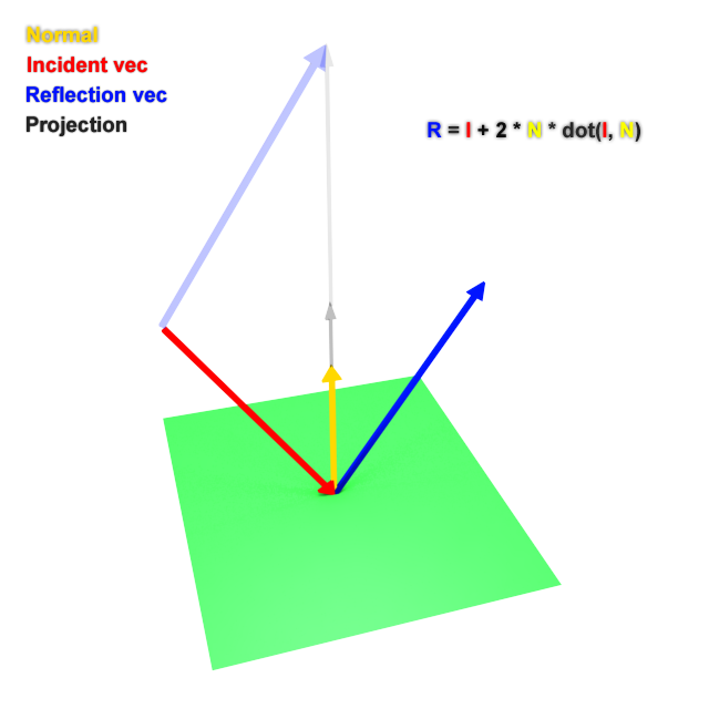
Vector3 reflectionVector = Vector3.Reflect(swimDirection, hit.normal);
float goalPointMinDistanceFromHit = 1f;
Vector3 reflectedPoint = hit.point + reflectionVector * Mathf.Max(hit.distance, goalPointMinDistanceFromHit);
// Set the goal point to halfway between the reflected point above
// and the tank center goal.
goalPoint = (reflectedPoint + tankCenterGoal.position) / 2f;
// Set the rotation we eventually want to achieve.
Vector3 goalDirection = goalPoint - transform.position;
goalLookRotation = Quaternion.LookRotation(goalDirection);
// Determine a danger level using a exponential scale so that danger
// ramps up more quickly as the fish gets nearer obstacle.
float dangerLevel = Mathf.Pow(1 - (hit.distance / obstacleSensingDistance), 4f);
// Clamp minimum danger level to 0.01.
dangerLevel = Mathf.Max(0.01f, dangerLevel);
// Use dangerLevel to influence how quickly the fish turns toward
// its goal direction.
float turnRate = maxTurnRateY * dangerLevel;
// Rotate the fish toward its goal direction.
Quaternion rotation = Quaternion.Slerp(transform.rotation, goalLookRotation, Time.deltaTime * turnRate);
transform.rotation = rotation;
}
}
/// <summary>
/// Draws visual debug aids that can be seen in the editor viewport.
/// </summary>
void DrawDebugAids()
{
// Draw lines from the fish illustrating what it "sees" and what
// evasive action it may be taking.
Color rayColor = obstacleDetected ? Color.red : Color.cyan;
Debug.DrawRay(transform.position, swimDirection * obstacleSensingDistance, rayColor);
if (obstacleDetected)
{
Debug.DrawLine(hitPoint, goalPoint, Color.green);
}
}
/// <summary>
/// Updates the fish's position as it swims.
/// </summary>
private void UpdatePosition()
{
Vector3 position = transform.position + swimDirection * swimSpeed * Time.fixedDeltaTime;
transform.position = position;
}
}
I think I can cut some out, such as the fish's wiggle stuff. Also, I've got a bit of work in front of me to pull together LERP, SLERP, and PerlinNoise functions. The LERP and SLERP should be easy. But I'm not familiar with PerlinNoise. I might be able to cut that out too though, but it looks like it could be useful later on. I'll just make UDTs for the Vectors and Quats.
And, I'm also just doing some "thinking out loud" on this thing. I knew this wasn't going to be easy. I'm just looking for the easiest path among the difficult choices.
Any software I post in these forums written by me is provided "AS IS" without warranty of any kind, expressed or implied, and permission is hereby granted, free of charge and without restriction, to any person obtaining a copy. To all, peace and happiness.
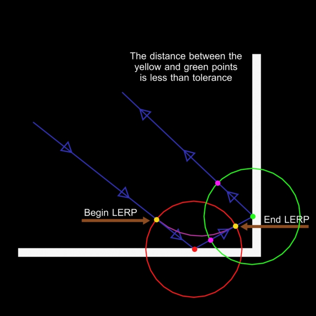
When your object comes close to the threshold, simply interpolate linearly between the current path and the reflected one (a & b on the picture(btw that's exactly the quadratic bezier curve)).
Last edited by The trick; Jan 28th, 2019 at 02:30 PM.
Thank you, Trick. I've studied your idea, and I like it. It sounds better than translating that C# code. And it gives me a concrete way to proceed.
From what I can tell, it's a linear interpolation for the velocity angle. For instance, prior to threshold point, we might say that we're progressing at a 45° angle (Theta1), and the reflected angle is 135° (Theta2). I will interpolate based on my Y position. We could say that threshold #1 is at Y1, and threshold #2 is at Y2.
Therefore, to figure out our current Theta progression angle, I find my current Y and interpolate between Theta1 and Theta2, with Y1 and Y2 as my base.
And then, I'm thinking I'll determine threshold points by using a percentage, say, 10% (or 90%) of then width (or height or depth) from a wall.
I'm still not quite sure what to do if we're heading in close to a corner, but this gives me something to work with. I knew that dynamically monitoring wall proximity was going to be part of the answer.
Any software I post in these forums written by me is provided "AS IS" without warranty of any kind, expressed or implied, and permission is hereby granted, free of charge and without restriction, to any person obtaining a copy. To all, peace and happiness.
This is what I was trying to suggest in post #7. As far as angles, Trick appears to be using physics: Angle of reflection = Angle of incident or Snell's law. Regarding a corner... in a 3D world, you have the z axis available also
If you plot the path vs. discovering the path, you can calculate this all in advance. For example, you know your angle/direction the path is heading and where the "wall" is relative to the last path point. So you know when to alter direction. Additionally, you may have some randomness to determine if the path should change before then and in what direction and how far from the current path point. All of that allows you to calculate the next path point. Rinse and repeat until your logic determines when the path end should join the path start, like a roller coaster.
If you want a perpetual moving point that finds obstacles as it moves, then that is a different logic track.
Edited: There are advantages for both the latter is pure randomness while the former is preplotted. However, one can preplot hundreds of paths which would give the appearance of randomness. Major advantage is that you don't need to be concerned with wall collisions after paths are plotted
Last edited by LaVolpe; Jan 29th, 2019 at 09:06 AM.
Insomnia is just a byproduct of, "It can't be done"
From what I can tell, it's a linear interpolation for the velocity angle. For instance, prior to threshold point, we might say that we're progressing at a 45° angle (Theta1), and the reflected angle is 135° (Theta2). I will interpolate based on my Y position. We could say that threshold #1 is at Y1, and threshold #2 is at Y2.
I think you can work without angles at all, just using the vector's algebra. Just find the normal to the collision surface and calculate the reflect vector like:
Last edited by The trick; Jan 29th, 2019 at 09:58 AM.
Ok, I'm actually coding now. Trick and LaVolpe, believe me, I'm reading and studying your comments. I just need to get something started.
To start, I've just got a ball bouncing around in a 3D cube:
Now, I've got to calculate an inner-cube, with the area between the inner-cube and the outer-cube being threshold area.
And then, I've got to figure out how to apply my LERP function (which is what I believe Trick (and maybe LaVolpe too) are suggesting).
Here's the code I've got now. Just a Form1 and a BAS module, nothing on Form1.
Form1 code:
Code:
Option Explicit
'
Dim vLastPos            As VecType
Dim vCurrPos            As VecType
'
Const dStepMag          As Double = 7#
Const dThreshold        As Double = 0.1   ' A proportion.
Const lTimerInterval    As Long = 5
'
Dim vCubeBound1         As VecType
Dim vCubeBound2         As VecType
'
Dim WithEvents tmr As VB.Timer
'

Private Sub Form_Load()
    Me.AutoRedraw = True
    Me.FillStyle = vbFSSolid
    Me.FillColor = &HFF0000
    '
    Me.ScaleTop = 1000
    Me.ScaleHeight = -1000
    Me.ScaleLeft = 0
    Me.ScaleWidth = 1000
    '
    vCurrPos.x = 1#  ' Just to give it a start.
    vCurrPos.y = 502#
    vCurrPos.z = 3#
    vLastPos.y = 500#
    '
    vCubeBound2.x = 1000
    vCubeBound2.y = 1000
    vCubeBound2.z = 1000
    '
    Set tmr = Controls.Add("VB.Timer", "tmr")
    tmr.Interval = lTimerInterval
    tmr.Enabled = True
End Sub

Private Sub tmr_Timer()
    Dim vDirection  As VecType
    Dim vNextPos    As VecType
    Dim dSize       As Double   ' Ranges from 10 to 50.
    '
    vDirection = VecSubtract(vCurrPos, vLastPos)
    vDirection = VecScale(VecNorm(vDirection), dStepMag)
    '
    vNextPos = VecAdd(vCurrPos, vDirection)
    If Not IsBetween(vNextPos.x, vCubeBound1.x, vCubeBound2.x) Then vDirection.x = -vDirection.x
    If Not IsBetween(vNextPos.y, vCubeBound1.y, vCubeBound2.y) Then vDirection.y = -vDirection.y
    If Not IsBetween(vNextPos.z, vCubeBound1.z, vCubeBound2.z) Then vDirection.z = -vDirection.z
    vNextPos = VecAdd(vCurrPos, vDirection)
    '
    vLastPos = vCurrPos
    vCurrPos = vNextPos
    '
    dSize = vCurrPos.z / 1000 * 40 + 10
    '
    Me.Cls
    Me.Circle (vCurrPos.x, vCurrPos.y), dSize, &HFF0000


    'Debug.Print VecString(vCurrPos)
End Sub
BAS module code:
Code:
Option Explicit

Public Type VecType
    ' This is used for both 3D spatial vectors, and Euler angles as well.
    x As Double
    y As Double
    z As Double
End Type
'
Public Type QuatType                      ' To get axis and theta back out (JPL convention):
    w As Double         ' cos(theta/2)              theta = ACos(q.w) * 2
    x As Double         ' v.x * sin(theta/2)        v.x = q.x / sin(theta/2)    solve for theta first, and then plug in here.
    y As Double         ' v.y * sin(theta/2)        v.y = q.y / sin(theta/2)
    z As Double         ' v.z * sin(theta/2)        v.z = q.z / sin(theta/2)
End Type
'
Public Const pi             As Double = 3.14159265358979
Public Const pihalf         As Double = 1.5707963267949
Public Const pidivby180     As Double = 1.74532925199433E-02
'

Public Function IsBetween(s As Double, bound1 As Double, bound2 As Double) As Boolean
    If bound2 > bound1 Then
        IsBetween = s >= bound1 And s <= bound2
    Else
        IsBetween = s >= bound2 And s <= bound1
    End If
End Function

Public Function IsInCube(uVtest As VecType, uV1 As VecType, uV2 As VecType) As Boolean
    ' uV1 and uV2 are 3D diagonal bounds for the cube.
    IsInCube = IsBetween(uVtest.x, uV1.x, uV2.x) And _
               IsBetween(uVtest.y, uV1.y, uV2.y) And _
               IsBetween(uVtest.z, uV1.z, uV2.z)
End Function

Public Function VecNorm(uV As VecType) As VecType
    Dim norm    As Double
    '
    norm = Sqr(uV.x * uV.x + uV.y * uV.y + uV.z * uV.z)
    If norm <> 0# Then
        VecNorm.x = uV.x / norm
        VecNorm.y = uV.y / norm
        VecNorm.z = uV.z / norm
    End If
End Function

Public Function VecMag(uV As VecType) As Double
    VecMag = Sqr(uV.x * uV.x + uV.y * uV.y + uV.z * uV.z)
End Function

Public Function VecLerp(uV1 As VecType, uV2 As VecType, ByVal s As Double) As VecType
    Dim s1  As Double
    '
    s1 = 1# - s
    VecLerp.x = s1 * uV1.x + s * uV2.x
    VecLerp.y = s1 * uV1.y + s * uV2.y
    VecLerp.z = s1 * uV1.z + s * uV2.z
End Function

Public Function VecAdd(uV1 As VecType, uV2 As VecType) As VecType
    VecAdd.x = uV1.x + uV2.x
    VecAdd.y = uV1.y + uV2.y
    VecAdd.z = uV1.z + uV2.z
End Function

Public Function VecNegate(uV As VecType) As VecType
    VecNegate.x = -uV.x
    VecNegate.y = -uV.y
    VecNegate.z = -uV.z
End Function

Public Function VecScale(uV As VecType, ByVal s As Double) As VecType
    VecScale.x = uV.x * s
    VecScale.y = uV.y * s
    VecScale.z = uV.z * s
End Function

Public Function VecSubtract(uV1 As VecType, uV2 As VecType) As VecType
    VecSubtract.x = uV1.x - uV2.x
    VecSubtract.y = uV1.y - uV2.y
    VecSubtract.z = uV1.z - uV2.z
End Function


Public Function VecString(v As VecType) As String
    VecString = Format$(v.x, "#0.00000") & ", " & Format$(v.y, "#0.00000") & ", " & Format$(v.z, "#0.00000")
End Function
I'll keep posting, as it helps me to stay motivated.
Any software I post in these forums written by me is provided "AS IS" without warranty of any kind, expressed or implied, and permission is hereby granted, free of charge and without restriction, to any person obtaining a copy. To all, peace and happiness.
And yes, I've decided to keep the 3D aspect, even in the beginning. I think I'll paint myself into a corner, if I do it first as 2D.
And here's what I'm currently struggling with:
I feel confident that I can deal with the orange dot (red lines) situation. I believe my VecLerp function will handle that without much ado.
However, it's that green dot situation I'm worried about. Once I'm in a corner-threshold (as opposed to a side-threshold), I believe I've got to LERP with that parallel line (and also find it so I can LERP with it).
Now, in 3D, 2D parallel lines don't need to be 3D parallel. However, it's just the same problem: Am I in a side-threshold, am I in a corner-threshold, am I in a cube-threshold? If I'm in a cube-threshold, I just have to find the 3D parallel line, and LERP with it.
I think I see it ... or at least I hope so.
Any software I post in these forums written by me is provided "AS IS" without warranty of any kind, expressed or implied, and permission is hereby granted, free of charge and without restriction, to any person obtaining a copy. To all, peace and happiness.
Trick, you're truly amazing. I've been struggling to get something similar to that up and running for the last day. I've sort of got something limping along, but it still has problems.
I get by with this linear algebra stuff, but it truly seems to be second-nature to you.
Yet again, MANY Thanks for your assistance,
Elroy
Any software I post in these forums written by me is provided "AS IS" without warranty of any kind, expressed or implied, and permission is hereby granted, free of charge and without restriction, to any person obtaining a copy. To all, peace and happiness.
When I've had time, I've been studying your code. As stated, I was working on the problem as well, but took a somewhat different approach, and that has made me wonder why you did certain things, and how they're applied. Specifically, I'm focusing on this code:
Code:
Public Sub Update()
    Dim fDistanceSq     As Single
    Dim fDistanceSq2    As Single
    Dim tNewColPoint    As tVector
    Dim fTheta          As Single
    Static bIsColDet    As Boolean

    ' // Calculate distance to collision point
    fDistanceSq = vec_length_sqr(vec_sub(mtPos, mtColPoint))

    If fDistanceSq <= mcRange.Tolerance Then

        ' // Collision detected
        bIsColDet = True

        ' // Calculate next collision point
        tNewColPoint = RecalculateCollisions(mtDir)

        ' // Get distance to that point
        fDistanceSq2 = vec_length_sqr(vec_sub(mtPos, tNewColPoint))

        ' // Check if that point is closer than previous
        If fDistanceSq2 < fDistanceSq Then

            ' // Update new collision point
            mtColPoint = tNewColPoint
            RecalculateReflection
            fDistanceSq = fDistanceSq2

        End If

        ' // Calculate affect
        fTheta = (((mcRange.Tolerance) - (fDistanceSq)) / (mcRange.Tolerance)) ^ 8

        ' // Update dir
        mtDir = vec_lerp(mtDir, mtReflVec, fTheta)

    Else

        If bIsColDet Then

            ' // If there was a collision
            ' // Update next point

            RecalculateReflection
            mtColPoint = RecalculateCollisions(mtDir)

            ' // ToDo: make smooth release speed
            mtDir = vec_normalize(mtDir)

            bIsColDet = False

        End If

    End If

    mtPos = vec_add(mtPos, vec_scale(mtDir, mfSpeed))

    ' // Drawing

    mcRange.Canvas.Circle (mtPos.fX, mtPos.fY), 10, vbRed

    If bIsColDet Then

        mcRange.Canvas.Line (mtPos.fX - 2, mtPos.fY - 2)-Step(4, 4), vbYellow, BF

        If mcRange.DrawOptions And DO_TOLERANCE Then

            mcRange.Canvas.FillStyle = vbFSTransparent
            mcRange.Canvas.Circle (mtPos.fX, mtPos.fY), Sqr(mcRange.Tolerance), vbCyan
            mcRange.Canvas.FillStyle = vbFSSolid

        End If

    End If

    If mcRange.DrawOptions And DO_REFLECTION Then
        mcRange.Canvas.Line (mtColPoint.fX, mtColPoint.fY)-Step(mtReflVec.fX * 20, mtReflVec.fY * 20), vbRed
        mcRange.Canvas.Circle (mcRange.Canvas.CurrentX, mcRange.Canvas.CurrentY), 1, vbRed
    End If

    If mcRange.DrawOptions And DO_COLPOINT Then
        mcRange.Canvas.Circle (mtColPoint.fX, mtColPoint.fY), 3
    End If

    If mcRange.DrawOptions And DO_DIRECTION Then
        mcRange.Canvas.Line (mtPos.fX, mtPos.fY)-Step(mtDir.fX * 20, mtDir.fY * 20), vbBlue
        mcRange.Canvas.Circle (mcRange.Canvas.CurrentX, mcRange.Canvas.CurrentY), 1, vbBlue
    End If

End Sub

Private Sub RecalculateReflection()
    mtReflVec = vec_get_refl(mtDir, mtColNormal)
End Sub
And more specifically, I'm looking at these couple of lines:
That's all somewhat similar to what I was thinking, but not precisely the same. Let me see if I can outline.
When we entered a "tolerance" zone, I was thinking we'd: 1) preserve our direction vector at that point; 2) calculate its reflection and save it; 3) for each movement, LERP between the original direction vector and the reflection, based on our distance between the two; and then 4) scale and add that LERPed direction to our position.
Now, our #1, #2, & #4 are the same. However #3 is different. You seem to be LERPing from your current direction to the reflection (rather than LERPing from the original direction to the reflection).
In addition, your LERP weight (fTheta) seems to be a number I don't understand at all. If our original vector and reflected vector are normalized, I'd just think that the LERP weight would be our current distance between those two, with the next step added. Admittedly, I hadn't worked out all the details of that, but that approach would seem to give us more consistency.
I'm going to research some more math algorithms on doing this, and try to see what others say.
Just some thoughts,
Elroy
EDIT: Let me also say that you've made me realize that, at any point in time, we will only be intersecting one line segment. And, extended to 3D, we will only be intersecting one plane segment. That helps me to conceptualize the problem. (I've got code to detect intersection with a plane segment.) In other words, we only need to worry about one upcoming collision at a time. I suppose we could be heading directly toward a corner. However, if we re-check our collision every frame (as you do), I don't think that's something we need to worry about.
Last edited by Elroy; Feb 1st, 2019 at 01:30 PM.
Any software I post in these forums written by me is provided "AS IS" without warranty of any kind, expressed or implied, and permission is hereby granted, free of charge and without restriction, to any person obtaining a copy. To all, peace and happiness.
Elroy, when an object reaches the range (given by tolerance) we need to ensure the new point isn't closer than the current collision one. Because without that we'll have the errors when the destination point is closer than current:
Therefore we need to check the distance between the next point and if it's less make reflection from that point rather current. In the my code i just check the distance whether we are within the tolerance zone or not. If the next point is closer i just assign the one to the current point and calculate the next one. It always corrects the direction within the tolerance zone (because you can have a non-rectangle/more complex range).
The affect value is calculating depending on distance because if a point has the big speed it can come to edge quite closer and therefore it need the bigger correction than others.
Option Explicit

Private WithEvents tmrClock As cTimer

Private Sub Form_Click()
    InitFishes NF
End Sub

Private Sub Form_Load()
    Randomize Timer
    InitFishes 3
    Set tmrClock = New_c.Timer(40, True)
End Sub

Private Sub Form_Resize()
    ScaleMode = vbPixels
    Set BBuf = Cairo.CreateSurface(ScaleWidth, ScaleHeight)
    RedrawOn BBuf.CreateContext
    Set Picture = BBuf.Picture    'finally set the updated content of the BackBuf-Surface as the new Form-Picture
End Sub

Private Sub tmrClock_Timer()
    RedrawOn BBuf.CreateContext
    Set Picture = BBuf.Picture    'finally set the updated content of the BackBuf-Surface as the new Form-Picture
End Sub

Private Sub Form_Terminate()
    New_c.CleanupRichClientDll
End Sub
Add a basic 2D vector helper module:
Code:
Option Explicit

Public Type tVector
    X             As Double
    Y             As Double
End Type

Public Function Vec2Len2(V As tVector) As Double
    With V
        Vec2Len2 = .X * .X + .Y * .Y
    End With
End Function

Public Function Vec2Normalize(V As tVector) As tVector
    Dim D         As Double
    D = Vec2Len2(V)
    If D Then
        D = 1 / Sqr(D)
        Vec2Normalize.X = V.X * D
        Vec2Normalize.Y = V.Y * D
    End If
End Function

Public Function Vec2Sum(V1 As tVector, V2 As tVector) As tVector
    Vec2Sum.X = V1.X + V2.X
    Vec2Sum.Y = V1.Y + V2.Y
End Function

Public Function Vec2Sub(V1 As tVector, V2 As tVector) As tVector
    Vec2Sub.X = V1.X - V2.X
    Vec2Sub.Y = V1.Y - V2.Y
End Function

Public Function Vec2MUL(V As tVector, Scalar As Double) As tVector
    Vec2MUL.X = V.X * Scalar
    Vec2MUL.Y = V.Y * Scalar
End Function
And Add the Fishes working Module:
Code:
Option Explicit

Public Type tFish
    Pos           As tVector
    Vel           As tVector
    Path()        As tVector
    pIDX          As Long
    '    nextpDist     As Double
    R             As Double
    G             As Double
    B             As Double
End Type

Public BBuf       As cCairoSurface
Private Const PI2 As Double = 3.14159265358979
Private Const InvPI2 As Double = 1 / 3.14159265358979
Private Const SideSize As Double = 512
Private Const SideHalf As Double = SideSize / 2    'let's work on a fixed (squared) SideSize here (512x512)
Private Const InvSideSize As Double = 1 / SideSize

Private Fish()    As tFish
Public NF         As Long

Private Const PathLen As Long = 4

Private Const MaxVel As Double = 5
Private Const MaxVel2 As Double = MaxVel * MaxVel


Public Sub InitFishes(N As Long)
    Dim I         As Long
    Dim j         As Long
    Dim K         As Long
    Dim D         As Double
    Dim Dx        As Double
    Dim Dy        As Double
    Dim MinD      As Double
    Dim NP        As Long
    Dim CP        As Long
    Dim TV        As tVector
    Dim Tvis      As Boolean
    Dim Visited() As Boolean

    NF = N
    ReDim Fish(NF)
    For I = 1 To NF
        With Fish(I)
            .Pos.X = Rnd * (SideSize) - SideHalf
            .Pos.Y = Rnd * (SideSize) - SideHalf
            .Vel.X = (Rnd * 2 - 1)
            .Vel.Y = (Rnd * 2 - 1)

            ReDim .Path(PathLen)
            For j = 1 To PathLen
                .Path(j).X = (Rnd * (SideSize) - SideHalf) * 0.75
                .Path(j).Y = (Rnd * (SideSize) - SideHalf) * 0.75
            Next

            '------------------- Sort Path
            ReDim Visited(PathLen)    'Clean up
            Visited(1) = True
            CP = 1: j = 2
            Do
                MinD = 1E+32
                For K = 1 To PathLen
                    If Not Visited(K) Then
                        If CP <> K Then
                            Dx = .Path(CP).X - .Path(K).X
                            Dy = .Path(CP).Y - .Path(K).Y
                            D = Dx * Dx + Dy * Dy
                            If D < MinD Then
                                MinD = D
                                NP = K
                            End If
                        End If
                    End If
                Next
                TV = .Path(NP)
                .Path(NP) = .Path(j)
                .Path(j) = TV
                Visited(j) = True
                CP = j
                j = j + 1
            Loop While j <= PathLen
            '-------------------


            .pIDX = 1


            Do
                .R = Rnd: .G = Rnd: .B = Rnd
            Loop While .R + .G + .B < 1.65

        End With
    Next


End Sub


Public Sub RedrawOn(CC As cCairoContext)    'the Main-Routine will render the entire scene

'  CC.Paint 1, Cairo.CreateSolidPatternLng(vbWhite)    'ensure white BackGround on the Form-Covering BackBuf-Bitmap
    CC.SelectFont "Courier New", 8, vbWhite
    CC.SetLineWidth 1

    PrepareCenteredCoordSystem CC

    DrawAndMoveFishes CC
End Sub


Private Sub PrepareCenteredCoordSystem(CC As cCairoContext)
    Dim X As Double, Y As Double, Dx As Double, Dy As Double
    Cairo.CalcAspectFit 1, BBuf.Width, BBuf.Height, X, Y, Dx, Dy, 64
    With CC
        .TranslateDrawings X, Y    'shift the placement of our square Draw-Area within the potentially "non-square" Form-Area
        .ScaleDrawings Dx * InvSideSize, Dy * InvSideSize    'adapt the scaling in relation to our fixed area-size
        .TranslateDrawings SideHalf, SideHalf    'shift the Coord-Sys into the center of our Area
        .AntiAlias = CAIRO_ANTIALIAS_GRAY
        .SetLineCap CAIRO_LINE_CAP_ROUND
    End With

End Sub


Private Sub DrawAndMoveFishes(CC As cCairoContext)
    Dim I         As Long
    Dim j         As Long
    Dim V         As tVector
    Dim P         As tVector

    Dim PathVec   As tVector
    Dim Vel2      As Double
    Dim InvD      As Double

    CC.Paint 1, Cairo.CreateSolidPattern(0.1, 0.1, 0.4, 0.55)

    For I = 1 To UBound(Fish)

        With Fish(I)
            '---------------------- DRAW ------
            CC.SetSourceRGB .R, .G, .B
            P = .Pos
            CC.Arc P.X, P.Y, 4
            CC.Fill
            CC.MoveTo P.X, P.Y
            CC.LineTo P.X + .Vel.X * 3, P.Y + .Vel.Y * 3
            CC.Stroke

            For j = 1 To PathLen
                CC.Arc .Path(j).X, .Path(j).Y, 1
                CC.Fill
            Next
            '----------------------------

            'Path Follow --------------
            PathVec = (Vec2Sub(.Path(.pIDX), .Pos))
            InvD = 1 / Sqr(Vec2Len2(PathVec))
            V.X = PathVec.X * InvD
            V.Y = PathVec.Y * InvD
            .Vel = Vec2Sum(.Vel, Vec2MUL(V, 100 * InvD))
            '------------------------

            'Limit VEL--------------
            Vel2 = Vec2Len2(.Vel)
            If Vel2 > MaxVel2 Then
                .Vel = Vec2MUL(Vec2Normalize(.Vel), MaxVel)
            End If
            '-----------------------

            ' MOVE--------
            .Pos = Vec2Sum(.Pos, .Vel)
            '------------

            If Vec2Len2(PathVec) < 100 Then    ' Go to Next path Point
                .pIDX = .pIDX + 1: If .pIDX > PathLen Then .pIDX = 1
            End If

        End With
    Next
End Sub
EDIT:
Anyway I think that to that to get good (better) results the best way is to use the "Craig Reynolds Boids" approach.
That's nice reexre. I might take a look at the logic. Thanks.
Any software I post in these forums written by me is provided "AS IS" without warranty of any kind, expressed or implied, and permission is hereby granted, free of charge and without restriction, to any person obtaining a copy. To all, peace and happiness.
3D Swimming Fishes implemented by Flocking Boids Algorithm.
Here it comes my 3D implementation using the aforementioned steering behavior.
Sorry if I do not add much to the description (maybe I'll do it in the future), now I'm a bit tired.
Some interesting features included in source code:
OCTREE: OctTree class for 3D collision detection.
Devrived from reexre QuadTree Class for 2D collision.
QuickSort: A QuickSort Algorihm used for sorting fishes draw-order
that can be used for other pourposes.
...
PS:
I need to improve the camera movement using the mouse (Form_MouseMove). Do you have any ideas?
...
I had some code I used to control eyepoint movement in an application. I had to do some minor adjusts to fit your X,Y,Z axis orientation, but I think it looks OK.
I track a pitch and yaw value to control the angle the camera is looking from, then generate the X,Y,Z offset values based on that pitch and yaw.
I limit the pitch (i.e.) the camera arc to +/- 90 degrees.
the yaw (rotation) will allow continuous 360 degree motion.
'Add a declaration at form scope.
Code:
Const Deg2Rad As Double = 3.1415926 / 180#
Private yaw As Double, pitch As Double
Then, in the Reset events (Command1_Click, cmdR_Click), and in the Form_Load add
Code:
yaw = 90: pitch = 0
Then, Case 1 in your MouseMove event is modified as follows.
Code:
    Case 1
      If chk3D.Value <> 0 Then    'don't modify pitch and yaw when we're not in 3D mode
        D = Sqr(vec3LEN2(vec3SUB(Camera.cFrom, Camera.cTo)))
        pitch = pitch - (Y - y0)
        yaw = (yaw - (X - x0)) Mod 360
        x0 = X: y0 = Y
        If pitch > 90 Then pitch = 90
        If pitch < -90 Then pitch = -90

        With Camera
            .cFrom.Z = D * (Sin(yaw * Deg2Rad) * Cos(pitch * Deg2Rad))
            .cFrom.X = D * (Cos(yaw * Deg2Rad) * Cos(pitch * Deg2Rad))
            .cFrom.Y = (D * Sin(pitch * Deg2Rad))
        End With
        UpdateCamera
      End If
p.s. {no longer valid, see p.p.s} Had to add 90 to yaw at camera calculation time, to match the orientation of the 2D view, so when you switch from 2D to 3D, you're looking at the fish from the same perspective initially. I guess you could just initialize yaw to 90, and reset it to 90 when you do the resets, so then wouldn't need to add 90 all the time.
p.p.s. Went ahead and changed the code to preset/reset to yaw = 90.
I had some code I used to control eyepoint movement in an application ....
Thank you very much !!! it Works fine !
( I suggest to attenute (Y - y0) and (X - y0) multipling them by EG 0.2 )
...And Remeber to add to cFrom-Vector the Camera target cTo-Vector.
(In this case it works without it because cTo is 0,0,0 )
I'll update my code and add this as sub CameraSetRotation(ByVal Yaw As Double, ByVal Pitch As Double) in module m3DtoScreen.bas
This module will be cleaned up and simplified. But I still have doubts about how to manage the points behind the camera.
It (m3DtoScreen) was taken long ago from here (World to Screen Projection Transformation
Written by Paul Bourke December 1994) and I like it very much because it do not use matrices or quaternions... just Vectors
...
...And Remeber to add to cFrom-Vector the Camera target cTo-Vector.
(In this case it works without it because cTo is 0,0,0 )
... But I still have doubts about how to manage the points behind the camera.
It (m3DtoScreen) was taken long ago from here (World to Screen Projection Transformation
Written by Paul Bourke December 1994) and I like it very much because it do not use matrices or quaternions... just Vectors
Yeah, I saw that you were looking at 0,0,0 so took the shortcut. I also thought about scaling the angle changes down, but at the normal scale, I figured the 1 degree per pixel movement was good enough.
{p.s. Note that is you do want to multiply by .2, then you'll want to remove the Mod 360 from the end of the line, because that ends up removing the values after the decimal point. If you move the mouse slowly, you won't rotate because the fractional addition won't accumulate, the (x-x0) keeps getting truncated to 0. You'll need to limit the value after the accumulation, without the Mod function.
Code:
        yaw = (yaw - 0.2 * (X - x0)) ' Mod 360
        If yaw > 360 Then yaw = yaw - 360
        If yaw < 0 Then yaw = yaw + 360
}
In the case where I have a zoom capability, then I do usually attenuate the angle change magnitude based on zoom, because if you zoom in, then viewing angle changes of 1 degree increments is much too coarse.
As for points behind the camera, the systems I've used usually have a cut-off that removes points that are behind a threshold that is actually in front of the camera. By default, on our flight simulation out the window, the value defaults to cutting out things that are close is 5 meters, but that is more for high flyers, not things that flight near the ground often, like helicopters. So, we changed those to cut off at 2 meters, but in other cases where the eyepoint is associated with a sensor that is mounted to the aircraft, and parts of the aircraft can obscure the view, then we'll choose a value that is a fraction of a meter in front of the camera.
Bottom like, you should not be processing points that are behind the camera, and not even ones that are even with the camera, necessarily.
The issue, I guess, is how quickly can you determine if the point is behind the viewing plane, and eliminate plotting the object, or truncating the point along the vector to generate a new point at the intersection of your viewing plane. I know I had some problems with that back in the day when I was trying out some of this stuff in VB3. My side wall images, could be rendered really out of whack, and twisted or flipped as I rotated the camera and points ended up (I assume) behind the camera. I didn't work that much with code where I was doing the 3D calculations myself, so didn't necessarily resolve my early experiments.
I found small bugs on my 3D fish (V1), I will fix them on next ZIP update.
- if you use QueryCube the check for D2 must be If D2 < MaxInteractDist2
- if you want to use QuerySphere this D2 check is not needed
Bug fix on Sub pvQuerySphere: Change pY to pZ here: rpZ(foundCount) = pZ
The problem of 3D points behind the camera or out of its view, regards drawing of lines and other objects, rather than points.
Points can simply be ignored, whereas if they are points that belong to other objects (like lines) they must be transformed.
I have to pay more attention to the original code mentioned above, as I think it also covers these cases.
Just an FYI to folks: I've done some work on this, and I see that others have posted some excellent ideas. However, I'm on a consulting gig for about 3 weeks, so this has taken the back burner. I will get back to it though.
Y'all Take Care,
Elroy
Any software I post in these forums written by me is provided "AS IS" without warranty of any kind, expressed or implied, and permission is hereby granted, free of charge and without restriction, to any person obtaining a copy. To all, peace and happiness.


 Reply With Quote

 LaVolpe, I can see I got your gears turning a bit.

 remove the fog in options


 !
!
