|

-
Apr 30th, 2012, 12:40 AM
#27
Re: Fun With Electricity
Fun With Electricity Part 3
This is one of my favorite experiments. In this experiment, you will be playing around with an actual NES controller. And can open doors for some modding such as this:
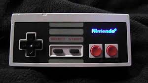
Or even this:
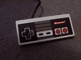
Or this:
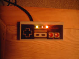
Trust me. Its easier than you think. And I'll show you how. Before we start. I wanna talk to you about how an NES controller works. Remember the 7 prongs at the end?
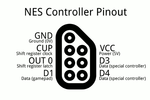
As you can see from the diagram. That's what they do. However, on an NES controller, only 5 are used because its not a Zapper, Power Glove, or any other special device. So disregard D3 and D4 which are reserved for special controllers. Now when you take apart your NES controller, you'll notice 5 different colored wires:
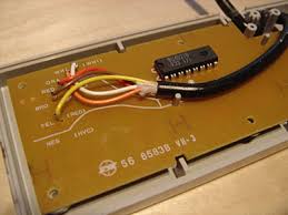
Here is what they do from top to bottom:
White: 5V DC Input
Orange: Shift Register Latch, or just Latch for short.
Red: Shift Register Clock, or just clock for short.
Brown: GND, also known as Ground. Duh.
Yellow: Data Out
You will also notice a chip on the circuit. This is known as a 4021 Shift Register. Although not that important in the experiment I am about to show you. Its simpler than you think to know what they do and can open doors for even more modding . Here is what each of the pins do:
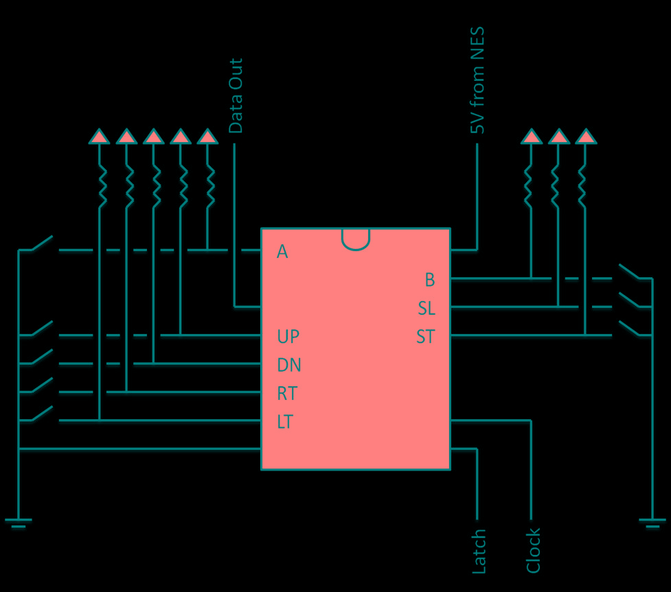
And if you follow your little eyeball in the back of the circuit boards little paths, you'll notice that they do in fact connect with those buttons.

Currently 5V DC is running through the circuit board with the NES on. (5V - 1.7) / 0.02 A = 165, which means the closest resistor you'll need is a 150 Ohm resistor. If you press the Start button, it will cause a short, showing start has been pressed. Same holds true with B, A, Select, Up, Down, Left, and Right. Knowing this, you can make LED lights light up when you press a button, which is cool if successfully pulled off, but we will do something different in this experiment. In this we will just light up a red LED.
In this experiment, you will need the following:
- NES
- NES Controller
- NES Power Supply and RCA cable
- Red and Black spare copper wires
- Alligator clips
- A 150 Ohm Resistor
- Red LED 1.7 Vf 20 mA
Step 1) Be sure your power is off before you begin. Take apart your NES controller by removing the 6 screws on the back. You'll only need the circuit board and cable for this experiment.
Step 2) Plug in your NES controller but keep the power off. Start with the red wire already pre stripped on both ends. Connect a Red alligator clip to one of the ends. Connect the other end of the alligator clip to a 150 Ohm resistor.
Step 3) Connect a White alligator clip to the other end of the resistor and on the other end of the White alligator clip, connect it to the long end of the red LED light, which is (+) positive.
Step 4) Connect a Black alligator clip to the short end of the red LED light, which is (-) negative. And on the other end of the Black alligator clip, connect a pre stripped Black wire.
Step 5) Next, remember the circuit board shown above?
On the right side of the image you'll see 5 large solder points. The top one as I already explained is 5V DC power. Place the free end of the Red wire on top of that and carefully clip it down using an alligator clip on the circuit board to hold it down. Don't try clipping the solder point itself, as it won't do it and just slip off.
Use the free Black end of the wire to place it on top of the 4th large solder on the right side. This is GND, or Ground. carefully use the other alligator clip and clip the wire down on the circuit board to hold it down. Since its kinda far from the alligator teeth, you'll just simply clip the wire itself down, which forces it down a notch. As long as the copper end is on top of the 4th solder point.
Step 6) Turn on your NES and watch it light up magically before your eyes. You can even mix experiment Part Two in this and add a dimmer switch. And with some slick soldering skills and a drill, you can even solder the same circuit to eliminate the need for alligator clips, and build your own LED lit NES controller. Happy modding /wave
Last edited by Jacob Roman; Apr 30th, 2012 at 12:45 AM.
 Posting Permissions
- You may not post new threads
- You may not post replies
- You may not post attachments
- You may not edit your posts
-
Forum Rules
|
Click Here to Expand Forum to Full Width
|


 Mark Thread Resolved
 Reply With Quote